
Hi Eva,
your description has me beat. The Pchannel in the +ve line has reverse control and similarly Nch in -ve line.
Onvynil,
the + &- halves of your schematic do not match.
+ve half collector to gate, -ve half base to gate.
If you have 24V on output then Vds is only 4V, so I think this may be right on the limit of operation of the FETs.
Consider +ve half control. If emitter is connected to 2*6.8V zeners then emitter voltage is -24+13.6=-10.4V. Base is at +24V, therefore Vbe=34.4V
A suitable zener would be 2 times 24V- 0.6V =47.4V.
But wait for Eva to reply because his description of the common source reg does not appear to work. If the toplogoy was changed to Source follower (swap N & Pch) then the control can be made to work.
I notice you want to use 6v8 Zeners. To get these into a good operating range it is normally recommended that they carry a minimum current of more than 10% of maximum. Using low voltage Zeners forces you to use very high current to meet this requirement.
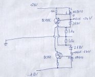
I'm sorry, I think you didn't understood my description. These are two versions of the simple regulator that I proposed. Note that it's not a source follower at all, and that the drain terminal (the tab of TO-220 devices) is conveniently grounded to allow to use a metal case directly as a heatsink.
The version on the left is the simplest one with only 5 components, but its minimum dropout voltage is determined by Vgs. The version on the right features a dropout voltage only limited by Rds-on at the expense of two additional components. The version on the left may require a zener for gate protection and some form of startup current limiting for the small transistor, while the version on the right has an inherent Vgs limitation to 17.6V (12V*1k/680) and the small transistor is protected.
Note that these are just simple circuits aimed at a low parts count and a lot of improvement may be obtained by just adding parts.
An externally hosted image should be here but it was not working when we last tested it.
The version on the left is the simplest one with only 5 components, but its minimum dropout voltage is determined by Vgs. The version on the right features a dropout voltage only limited by Rds-on at the expense of two additional components. The version on the left may require a zener for gate protection and some form of startup current limiting for the small transistor, while the version on the right has an inherent Vgs limitation to 17.6V (12V*1k/680) and the small transistor is protected.
Note that these are just simple circuits aimed at a low parts count and a lot of improvement may be obtained by just adding parts.
Argh, this strange arrangement makes me dizzy, I looked for Vbc instead of Vbe.AndrewT said:
Consider +ve half control. If emitter is connected to 2*6.8V zeners then emitter voltage is -24+13.6=-10.4V. Base is at +24V, therefore Vbe=34.4V
I notice you want to use 6v8 Zeners. To get these into a good operating range it is normally recommended that they carry a minimum current of more than 10% of maximum. Using low voltage Zeners forces you to use very high current to meet this requirement.
[/QUOTE]
Thanks for the hint.
Rüdiger
Obviously *loool*Eva said:I'm sorry, I think you didn't understood my description.
Thanks for clearing,
Rüdiger
richie00boy said:Have you considered an LM317T ? That will use less parts and be smaller and easier to wire up, and probably regulate better as well.
It all depends on voltage and current requirements. LM317 is quiet and precise, but it has its limitations in comparison with some standard power MOSFET like a IRF540 when the requirements are just a high output current and a very low dropout voltage.
By the way, I've seen a lot of people with their brand-new transformers producing too high voltages for their amplifiers and asking for some simple high-efficiency anti-overvoltage pre-regulator. This circuit may be very useful for them.
Yes, I intentionally arranged it this way to show the possibility of grounding the tabs of the TO-220 devices and using the metal case of the project as a heatsink without mica or sil-pad insulators nor plastic washers. This requires independent floating transformer windings for each supply (not center tapped), though.
Having floating transformer secondaries also allows to employ cheaper N-channel devices for both positive and negative rails, altough the tabs of the power devices from the negative rail won't be gounded and would require insulation.
Having floating transformer secondaries also allows to employ cheaper N-channel devices for both positive and negative rails, altough the tabs of the power devices from the negative rail won't be gounded and would require insulation.
Only the transformer winding is floating in that design and this is fine as long as the same winding is not employed for anything else. The output of the regulator is not floating, it's grounded... In fact it's ground! 
This ground is the one you should use for the rest of the circuit.
This ground is the one you should use for the rest of the circuit.
- Status
- This old topic is closed. If you want to reopen this topic, contact a moderator using the "Report Post" button.
- Home
- Amplifiers
- Power Supplies
- PSU with Simple Source Follower Regulator