Hello Forum-Friends,
Here is a simple high voltage regulator circuit that can provide +/- rails from around 30v to over 100v at a few hundred milliamps.
I developed it as part of another project, but it never got included. Hopefully some forum-goers can find a use for it.
Many of the components were selected to take advantage of broken / discarded computer powers supplies (they seem to be everywhere).
The attached PDF contains the schematic, a brief (very brief) description plus PCB layout and tracks.
Cheers
Attachments
Thanks for the schematic Quasi! This is what I have been looking for. Anyhow, I have a question...
I need this circuit to replace some circuit that I use for front-end supply of my amplifiers. I just copy the circuit (from other amp) without knowing precisely how to adjust for different Vi and Vo.
So I wanted to build "simple" circuit like this as a benchmark.
The question is, is this circuit suitable for front-end supply of state-of-the-art amplifiers? I need Vo=56V for my Stochino amplifier.
jackinnj said:just to be safe, you should put a 1N4007 anode connected to the top of R3, cathode to the input node (junction of D3,D4)
and vice-versa for the negative supply.
Yes Jackinnj is quite right regarding the diodes. If the input supply goes short cct for whatever reason, any residual voltage on the output will cause large currents to flow through the now reverse biased regulators and through the shorted input. Though this would be a fault event anyway, there's no point in destroying the regulators.
I have updated the schematic and layouts to include the diodes.
Thanks Jackinnj.
Attachments
Thanks Quasi. I had to cancel my question to Jackinnj regarding the possible damage due to inexistence of the diode ") Honestly, I don't care with the 7812s. I'm worrying the transistors I have matched from more than a thousand pieces
Honestly, I don't care with the 7812s. I'm worrying the transistors I have matched from more than a thousand pieces
In case I can't find the transistors (but I have many of that type from amplifier drivers), what is the minimum requirement (ie Vce) from the transistor for 40Vac (56Vdc)?
Is 330uF enough or more is better? I have 220uF Cerafines and 680uF Blackgates. On board, already installed are 220uF Cearfine and 10uF Solen.
Honestly, I don't care with the 7812s. I'm worrying the transistors I have matched from more than a thousand pieces In case I can't find the transistors (but I have many of that type from amplifier drivers), what is the minimum requirement (ie Vce) from the transistor for 40Vac (56Vdc)?
Is 330uF enough or more is better? I have 220uF Cerafines and 680uF Blackgates. On board, already installed are 220uF Cearfine and 10uF Solen.
Are you talking about the transistors used in this regulator board or transistors you are using in your amplifier?
The transistors used in th regulator board do not need to be matched, but they do need to be very robust.
If you are seeking comment about transistor voltage requirements in your amp I will need to see the cct.
For this regulator boards capacitors, more is better. For the input say up to 1,000 uF and up to 100uF for the output.
Cheers

quasi said:Are you talking about the transistors used in this regulator board or transistors you are using in your amplifier?
The transistors used in th regulator board do not need to be matched, but they do need to be very robust.
I was afraid a failure related to the 1N4007 might destroy the amplifier (with it's matched transistors). You explained that it wouldn't. I also thought may be I could use those transistors used as drivers in amplifiers (which I have plenty on hand). But I have checked the database and this 13007 is different with the driver transistors. Luckily I can source 13007, not MJE but SGS-Thomson one. I think MJE is more robust? I will try MJE later.
quasi said:If you are seeking comment about transistor voltage requirements in your amp I will need to see the cct.
Attached is one sample of regulator I'm using. How should I modify it for different voltages? How is it's relative quality?
quasi said:For this regulator boards capacitors, more is better. For the input say up to 1,000 uF and up to 100uF for the output.
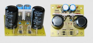
I have completed one board using 220uF input and 47uF (plus 100n) output. Small, because the PCB is also small.
I'm completing another board using 680uF (close enough to 1000uF) input and 220uF (plus 100n) output.
I'm also planning on another PTP board with massive input capacitance. I have plenty of Panasonic 680UF. But I hope the second board with 680uF (BlackGates) will not be worse than the third board.
Attachments
The 1N4007 was added only to save the regulators (7812 & 7912) if a particular fault occured. They do not affect the normal operation of the cct and would make any difference with your amplifier.
The 13007 is intended as a switching transisor and this is how it is used in the high voltage regulator. It has very low gain so it is not suitable as a driver transistor. It can be used as an output transistor for a general purpose amplifier, but there are better transistors around.
In the regulator circuit you posted, different voltages can be achieved by changing the zener. This sets the voltage for the regulator less around a volt for th transistors.
The circuit you posted is a discreet transistor regulator and variations of this can be found in many applications. It is of a reasonable quality but IC regulators are better.
The circuit I posted uses IC regulators and these achieve very good ripple rejection and low noise. To some degree they are similar to your circuit but in one TO220 package.
Cheers
Hello all,
FYI, the Texas Inst. TL-783C is a 3 terminal hi-v regulator. It uses a voltage divider between the output and the adj pin. It has a 125 volt max Vin to Vout rating. No zeners needed. Two resistors, 2-3 caps and you're home.
I have used it many times and it works great. You can even use it for higher voltages than 125 Volts. The TI apps engineer I asked, explained that the time constant of the input filter means that the Vin will ramp up, and as long as you aren't dropping more than the max 125 volts across the TL-783C, you are fine. I've used it with B+ supplies of over 300 volts with no problems.
Hi Tone22,
I did a search on the web some time ago and found the TL-783C. It does look like a very nice regulator and it can handle some power too.
But I needed a negative rail as well working off a common ground with something else. This meant I had to use a negative high voltage regulator and this I could not find.
So off to the drawing board I went....and by using the most common components came up with this.
Cheers
Hi Jay,
both sides of the ltp bases come from the regulated side of the supply.
The left side monitors the output voltage and corrects the feed to the darlington.
The right hand side takes the output voltage and subtracts 10V (zener) and feeds this straight to the base.
Is the Zener in the correct place? Swap it with the lower leg resistor? and use constant current feed into the zener regulated reference for the base.
Hi AndrewT,
I was actually expecting that kind of comment regarding the posted schematic! I don't understand electronics but I thought I saw something wrong. I didn't think about ccs thou. This schematic I took from LFA-50 or something amplifier (This is what I have access from work).
But Quasi has explained about it's relative quality with the IC based regulator, so I decided to concentrate on Quasi's cct. Later I will find possibility using 7815 (because I know that LM340 in TO-3 is better sounding) to replace the 7812.
Jay said:
I'm completing another board using 680uF (close enough to 1000uF) input and 220uF (plus 100n) output.
I'm also planning on another PTP board with massive input capacitance. I have plenty of Panasonic 680UF. But I hope the second board with 680uF (BlackGates) will not be worse than the third board.
You are not yet straying into the vicinity of over-damping the regulator's response -- but too high a capacitance value on the output increases the amount of time that it takes the error amplifier in an off-the-shelf regulator to respond.
jackinnj said:
You are not yet straying into the vicinity of over-damping the regulator's response -- but too high a capacitance value on the output increases the amount of time that it takes the error amplifier in an off-the-shelf regulator to respond.
Hmmm so that's the reason for a "maximum" value... Quasi said up to about 100uF output cap, and I planned 220uF output (because that's what I have on hand for 100V). The massive caps are for input, not output. Quasi said "up to 1000uF" for the input. Is there similar reason for such a low capacitance limit?
Yes, my intuition is that the limitation of this circuit is on the 7812 (that's why I'm looking for possibility to use LF340 in TO-3). I don't know if the major device in this cct could be the 13007, not the 7812...
Oh, wait... I have another 220uF+8.2uF on board, so it counts for the output cap
But using smaller caps in parallel will help a bit, won't it? I can make 100uF output from Solen MKP which I know is good for power supply The suggestion for up to 1,000uF of input capacitance has more to do with the smoothing of AC applied directly to the board. For a current of a few hundred milliamps this is sufficient. You could go for more but not a lot of benefit would be achieved and extra strain would be placed on the rectifier diodes.
The major devices in the circuit are the 7812 & 7912. The MJE13007's are only turned on momentarily when the circuit is first turned on, while the output capacitors (and capacitors in attached circuits) are charged. Once this is done only the regulators are actiive.
To put it another way MJE13007s simply protect the regulators when the circuit is first turned on. Under this condition the brief voltage across the regulator would have been more than it can handle.
The circuit at first glance could look like it uses the transistors as a booster stage carrying the bulk of the current but this arrangement is different.
Finally the circuit will work with any 3 pin regulator any 78xx & 79xx. The ouput voltage will be the sum of the zener(s) plus the regulator voltage.
Cheers
- Status
- This old topic is closed. If you want to reopen this topic, contact a moderator using the "Report Post" button.
- Home
- Amplifiers
- Power Supplies
- Basic high voltage regulated supply