Yes, it is possible, but it implies dealing with more than 700 volts from drain to source instead of 350V and requires two matched primary windings that should be as coupled as possible to reduce inductive spikes at turn-off. Furthermore, these spikes are quite hard to clamp because there is not a +700V supply rail but a +350V one, unlike in a full bridge or push-pull where the body diodes of the MOSFETs clamp the spikes to the supply rails.
12V push-pull power supplies suffer from the same inductive spike issues, but the MOSFETs employed are usually rated at 60V thus avalanche is not likely to happen (note that 60V is 5 times 12V). However, in a 230V AC off-line push-pull converter the switches would probably be rated between 800V and 1200V, thus leaving little voltage margin for inductive spikes before avalanche voltage is reached (note that your switches are rated at 800V, it's less than 3 times 300V altough it may be enough if you can figure out a good clamping approach).
12V push-pull power supplies suffer from the same inductive spike issues, but the MOSFETs employed are usually rated at 60V thus avalanche is not likely to happen (note that 60V is 5 times 12V). However, in a 230V AC off-line push-pull converter the switches would probably be rated between 800V and 1200V, thus leaving little voltage margin for inductive spikes before avalanche voltage is reached (note that your switches are rated at 800V, it's less than 3 times 300V altough it may be enough if you can figure out a good clamping approach).
Tekko said:You need to make like in the ESP car smps schem, use a npn and pnp bipolar transistor, one to turn the fets on and one to discharge the gate capacitance to allow the fets to switch as they should, otherwise it will not work. The SG3525 cannot drive the fets directly as its open collector and too low current handling.
Tekko,
I think you're referring to the output stage of the TL494, which has uncommitted emitters and collectors. The SG3525's outputs are true totem-pole outputs, though not as robust as later PWM ICs, like the MC33025 or the UC3825 (high-speed current-mode PWMs), which can drive +/-2A into highly capacitive loade, like MOSFETs with really BIG gate capacitance.
The '3525 is only good for +/-400mA pulsed, amd +/-200mA steady-state. However, this is good enough for driving the gate-drive xfmrs Eva described, or even IR211X hi-side and low-side MOSFET floating-gate driver ICs, which also have the +/-2A output current rating.
Hope this clears things up a little further.

Steve
Yes, I do design SMPS but I'm not yet in business, and given the SMPS migration that the PA market is experimenting, I can't provide such a ready-made schematic to you for free because I still expect to make some profit from my work before other people could start cloning and selling my prototypes like crazy... Sorry.
Eva said:Yes, I do design SMPS but I'm not yet in business, and given the SMPS migration that the PA market is experimenting, I can't provide such a ready-made schematic to you for free because I still expect to make some profit from my work before other people could start cloning and selling my prototypes like crazy... Sorry.
ok.
In this thread I explained how to figure out power transformer turn ratios for isolated buck converters: http://www.diyaudio.com/forums/showthread.php?s=&threadid=66801&highlight=
And this one contains the formula that allows to calculate the required primary turn count for a given core, frequency and flux density: http://www.diyaudio.com/forums/showthread.php?s=&threadid=63878&highlight=
For a gate drive transformer I wouldn't go above 200mT in worst case (ie: B=0.2). I can't provide any exact turn count value because it depends on core size and operating frequency. You'll have to calculate it by yourself.
Hi Nejc_car,
Please take a look to :
http://www.qrp4u.de/docs/en/smps_new/
Described as half bridge design, with junk parts. Good for start to try. Make small and reliable first then think to build thousand watts.
Please take a look to :
http://www.qrp4u.de/docs/en/smps_new/
Described as half bridge design, with junk parts. Good for start to try. Make small and reliable first then think to build thousand watts.
Hi, everybody
Here is an update on my project. I have made new Fet driving board, where I used gate trafo from old PC supply. It is configured as Half-bridge
This is how the signals look on gates of the fet´s.
Now the frequency is 38,4 kHz
5V/div
And the whole switching signal. 5V/div
I will post scheme of the gate drive soon
Here is an update on my project. I have made new Fet driving board, where I used gate trafo from old PC supply. It is configured as Half-bridge
An externally hosted image should be here but it was not working when we last tested it.
This is how the signals look on gates of the fet´s.
Now the frequency is 38,4 kHz
5V/div
An externally hosted image should be here but it was not working when we last tested it.
And the whole switching signal. 5V/div
An externally hosted image should be here but it was not working when we last tested it.
I will post scheme of the gate drive soon
Here is the schematic.
An externally hosted image should be here but it was not working when we last tested it.
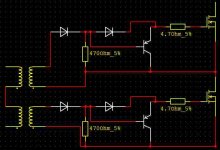
Passive resistive gate turn-off is not suitable for SMPS at all. Use a PNP buffer instead, with a diode to bypass it during turn-on.
The two latter schematics from that picture should be a good hint for turn-off improvement (for your case, replace the first NPN transistor by a diode as the one you are already employing to isolate negative pulses).
Be careful with pulse transformer ringing as it may cause parasitistic turn-on of the wrong set of MOSFETs, shall it happen RC damping networks would have to be added to the windings.
The two latter schematics from that picture should be a good hint for turn-off improvement (for your case, replace the first NPN transistor by a diode as the one you are already employing to isolate negative pulses).
An externally hosted image should be here but it was not working when we last tested it.
Be careful with pulse transformer ringing as it may cause parasitistic turn-on of the wrong set of MOSFETs, shall it happen RC damping networks would have to be added to the windings.
 on it
on it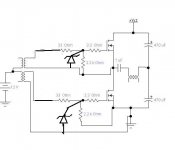
The gate drive approach as you show it should work fine. However, in the schematic both secondaries are driving the MOSFETs with the same polarity, but I suppose that this is just a typo as such a connection willl autodestruct itself. Also, two transformers with their primaries connected in series are shown, is that also a typo? A single transformer is preferable, since two transformers will require their primaries to be wired in paralell and some speacial means of flux balancing.
Have you placed a 1uF non-polar cpacitor between one of the primary leads of the transformer and the SG3525? This is essential to avoid transformer saturation. A couple of 2.2 ohm series resistors may also help in order to keep the SG3525A happier (they will help to prevent overshoot and will isolate it from transformer capacitances). Note that in case you are using two independent transformers, each one will require its own balancing capacitor and resistors.
By the way, how is your SG3525A wired to the transformer and to the rest of the circuit? Could you post an schematic? The problem may be here.
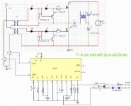
You are driving the transformer in the wrong way because the primary must be effectively shorted during the time MOSFETs are off, but your circuit just leaves it in a high impedance state and thus free to ring and turn on both MOSFETs ramdomly.
Also, base resistors for Q1 and Q2 are missing, is this a schematic typo?
If you want it to work properly, you have to drive the transformer directly from the OUTA and OUTB outputs of the SG3525A (or any other totem-pole low impedance source) with a 1uF series capacitor (and optional series resistors) as I previously mentioned. If the transformer has a 1+1:1+1 ratio, you should connect both primaries in paralell if you can, otherwise you should drive only one of the primaries, or drive both in series by employing a higher power supply voltage for the SG3525A (it's rated up to 35V). Either way, the supply voltage should be chosen to get 15V at the gates in order to achieve optimum conduction losses.
EDIT: Remember to ground both the Sync and Shutdown inputs, as they may pick up noise and cause the SG3525A to terminate the pulses or the clock cycles prematurely (big trouble). Also, you should place a capacitor of at least 10uF between Vc and Gnd pins, as the totem-pole output stage of that IC suffers from brief cross-conduction pulses in each transient.
- Home
- Amplifiers
- Power Supplies
- Offline full-bridge SMPS… need help