I am building a offline full-bridge SMPS and with no success.

I am using ETD-49, with input voltage of 230Vac(rectified 330Vdc), output +-30V,I curently have winded pri 21, sec 5+5, the fet's are BUZ80 and IC is SG3525, I use active feedback with optocoupler.
I don't know what frequency to use, I am corrently at 100kHz. With no load output goes to +-31V, but when I put for load 230Vac/60w lamp, output voltage drops to +-10V. Only two fet's start to heat up (no heatsink).
Does anyone have a working offline smps, i would very much like to see some schematics (pcb).
Any assistance would be much appreciated.
I am using ETD-49, with input voltage of 230Vac(rectified 330Vdc), output +-30V,I curently have winded pri 21, sec 5+5, the fet's are BUZ80 and IC is SG3525, I use active feedback with optocoupler.
I don't know what frequency to use, I am corrently at 100kHz. With no load output goes to +-31V, but when I put for load 230Vac/60w lamp, output voltage drops to
+-10V. Only two fet's start to heat up (no heatsink).Does anyone have a working offline smps, i would very much like to see some schematics (pcb).
Any assistance would be much appreciated.
But... If you have designed your transformer for a certain flux density, then you are supposed to know the optimum frecuency because... It's a design parameter!
Aren't you using almost random turn counts? I suppose you are, so the best thing you can do now is search that forum for transformer design hints and formulas.
Also, you should never use swiching devices without a heatsink, at least for experimentation, since the slightest mistake will cause a lot of trouble (switching devices without heatsink are only suitable for very low power applications anyway).
Concerning unequal heating of switching devices, it's usually caused by transformer flux imbalance and/or asymmetric gate or base drive.
And finally, if you provide some schematic and/or explain to us your regulation, gate drive and output filtering approaches in detail, we may be able to help you.
Aren't you using almost random turn counts?
I suppose you are, so the best thing you can do now is search that forum for transformer design hints and formulas.Also, you should never use swiching devices without a heatsink, at least for experimentation, since the slightest mistake will cause a lot of trouble
(switching devices without heatsink are only suitable for very low power applications anyway).Concerning unequal heating of switching devices, it's usually caused by transformer flux imbalance and/or asymmetric gate or base drive.
And finally, if you provide some schematic and/or explain to us your regulation, gate drive and output filtering approaches in detail, we may be able to help you.
Check this site: http://schmidt-walter.fbe.fh-darmstadt.de/smps_e/smps_e.html It may shed some light on your problem.
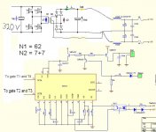
Oh come on, dont tell us that you drive high-side T1 T3 mosfets and low-side T2 T4 mosfets directly from SG3525 ?Nejc_car said:This is how the schematic looks like. Now my ratio of trafo is 62:7+7, but It delivers only 2V. Frequncy now is 62kHz.
Nejc_car said:NO. I im using 100 ohm gate resistors.

You CANT control n-mosfet full-bridge directly with 100ohm gate resistors as highside mosfets gate should be 345v relative to ground and lowside should be 15v relative to ground. You have blown already your controller/mosfets/gate resistors/all if trying to do that.
You need gate drive transformers, but before that study A LOT more about smps before you blow yourself instead of your bridge.
Given your now evident lack of experience, I would recommend some experimentation with low-voltage SMPS first, for example 30..50V input (rectified from some transformer) and +-30V output. This would allow you to learn in a safer way and to experiment with different full-bridge gate-drive approaches.
Actually, I test the first versions of my off-line SMPS prototypes with 50V or so before going to higher voltages.
Also, do you understand the concept of isolated gate drive?
The gates of the upper side MOSFETs must be driven with a voltage relative to its source voltage, whatever it is, not to the sources of the lower MOSSFETs and ground. This means that you can't just connect these gates to the outputs of the control IC, you have to take the voltage at the driver IC outputs (relative to ground) and make it relative to the sources of the high side MOSFETs, which are floating (not related to ground) and follow both terminals of the primary winding of the transformer. The most straightforward way to achieve that is by means of a pulse transformer. Search this forum on that topic...
PD. your schematic is conceptually wrong, the first single-ended filter shown, the one connected to the diodes, shouldn't be there.
mzzj said:
You CANT control n-mosfet full-bridge directly with 100ohm gate resistors
i use 100 ohm gate res. with no problems.
You need to make like in the ESP car smps schem, use a npn and pnp bipolar transistor, one to turn the fets on and one to discharge the gate capacitance to allow the fets to switch as they should, otherwise it will not work. The SG3525 cannot drive the fets directly as its open collector and too low current handling.
Also you need to adjust the voltage feedback for the desired output, this is easiest done with a pot.
Also you need to adjust the voltage feedback for the desired output, this is easiest done with a pot.
Tekko said:You need to make like in the ESP car smps schem, use a npn and pnp bipolar transistor, one to turn the fets on and one to discharge the gate capacitance to allow the fets to switch as they should, otherwise it will not work. The SG3525 cannot drive the fets directly as its open collector and too low current handling.
Also you need to adjust the voltage feedback for the desired output, this is easiest done with a pot.
his design omits bjt's.he says sg is capable to directly drive gates(100 ohm res req.).i used that design and smps is happily working in car.
You all have misunderstood the gate drive issue and the point of the whole thread. We were talking about high side drive in a full bridge off-line application, not about gate buffering nor 12V SMPS.
Obviously, such high side MOSFETs require a floating drive scheme, they can't be directly connected to a SG3525.
Obviously, such high side MOSFETs require a floating drive scheme, they can't be directly connected to a SG3525.
Eva said:You all have misunderstood the gate drive issue and the point of the whole thread. We were talking about high side drive in a full bridge off-line application, not about gate buffering nor 12V SMPS.
Obviously, such high side MOSFETs require a floating drive scheme, they can't be directly connected to a SG3525.
thanks for making this clear.
When designing such a transformer, leakage inductance should be minimised while maximising coupling between windings.
In practice, this is achieved by using the minimum number of turns that guarantees absence of core saturation for the operating frequency, voltage and temperature range, while filling the available width of the coil former (not including creepages). Sometimes, it's useful to wind bifilar or to split the primary in two (series or paralell) halves with the secondaries placed inbetween, etc...
The previous recommendations also apply to power transformers. You should figure out the optimum core size and magnet wire diameter.
The reason for a low leakage inductance is required in gate-drive transformers is that MOSFET turn-off times depend directly on it. When gate buffering is employed leakage inductance is no longer critical, though, but at the expense of an increased component count.
- Home
- Amplifiers
- Power Supplies
- Offline full-bridge SMPS… need help