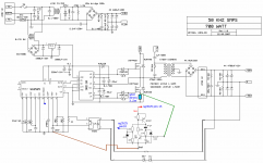
Found this on net, check drive for FET'S simpler,protection looks solid,you can use your resistors in lower FET source if you like but what a power waste,current transformer best solution.
thanks chas 1 for the quick reply is the schema you send good ? i can change mine to resemble your schema . also is the protection o.k and sensitive to over current ? .
also can any of the below igbt be useful with ee55 to give 3.5kwt ? i have them from old ups.
IRGP30B120KD-E , IRG4PH40UD2 , K30N60 , IRG4PF50WD , k40T120 , IRG4PC50U , IRG4PC40U , if i use them with a fsw of 100khz.? ? thanking you in advance steve.
As for the current limit it can be adjusted over a wide range,the idea is when the SCR trips it shuts down the osc and I think you need to look at some of the waveforms to see the effect.I set my limits for about 10% over current for the load.If you use a standard current transformer from Coilcraft they spec the burden resistor per amp so the setup is easy.If you have some softstart then the only time it should trip is at your over current set point.By using LTspice you can simulate this design to get an idea of the problems.
Last edited:
How about the design you posted or Luca's and there are more of them as for protection for the supply , downstream load or what?What control IC are you using as this will determine the type of protection that can be applied.The SG3525 has a shutdown pin as well as the IR2110,the MC33025 can be configured to monitor the current on a pulse by pulse basis, so by changing the control IC and the driver IC you can design a robust protection scheme.Refer to chapter 8 of High Frequency Switching Power Supplies Theory & Design by George Chryssis.I will post an LTspice of a couple of current limit circuits as well as the simulation files so you can try them later,you must have LTspice its a free download and the basic learning curve is short.I have played with a micro to handle my protection but its overkill in most designs.As for adding resistance to the low side FET in a HB I don't like as it adds voltage drop on the low side, ok for forward converter as the Fets are on at the same time.As for a stable High power supply don't rule out the Two Switch forward, designs for over 5kW
exists.
exists.
Last edited:
 cool link
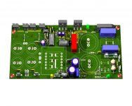
 my latest lay out. but i will use external aux +12vlts
Attachments
-
smps half bridge irfp460 smps single sided schematic.pdf34.1 KB · Views: 740
-
 smps half bridge irfp460 smps single sided.jpg277.8 KB · Views: 1,242
 -
smps half bridge irfp460 smps single sided components .pdf37.8 KB · Views: 551
-
smps half bridge irfp460 smps single sided pcb bottom .pdf46.7 KB · Views: 576
Hi Stewin, long time. According to mosfet datasheets, the maximum pulsed drain current is much higher (four times in IRFP 460- 80A) than the maximum continuous current. Since in smps the primary current is pulsed, I assume the maximum pulsed drain current is used when selecting a mosfet. Is there anyone who has had a mosfet failure related to overcurrent in the primary? That is assuming it was not dead time related failure.
Regards.
Regards.
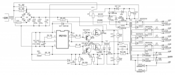
hi all by the way my above project worked perfectly with some few adjustments. i used irf740 and all was powerfull and o.k
now i wanted to do one with protection and transformer gate drive . as to do a full bridge in the near future.
now i wanted to do one with protection and transformer gate drive . as to do a full bridge in the near future.
Attachments
-
smps half bridge single sided transfo drive schema.pdf36.1 KB · Views: 404
-
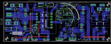 smps half bridge single sided transfo drive board tracks.jpg267.4 KB · Views: 1,034
 -
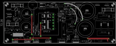 smps half bridge single sided transfo drive board.jpg187.9 KB · Views: 967
 -
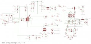 smps half bridge single sided transfo drive schema.jpg259.3 KB · Views: 978
 -
smps half bridge single sided transfo drive artwork.pdf310.9 KB · Views: 465
Last edited:
ATLK6 smps simulation
In this thread the the K6 smps there were questions if it worked as designed, so I am posting all the LTspice simulations I used to simulate the design and you can be the judge.In order to run the simulations you must have a copy of LTspice which is a free download, then make a folder in LTspiceIV and name it atl or any other name you choose.Remember to make simulations run faster only the bare bones are used but I think its ok.I have tested the zip file( I used Jzip) is complete but if have problems or you get an error that something is missing, let me know.Feel free to comment or make additions as this might help other DIY who lack spice experience.I tested the 42volt,56volt and 82 volt outputs as well as simulating a short on the outputs,by no means is this a complete design it is only for simulation,try it..
In this thread the the K6 smps there were questions if it worked as designed, so I am posting all the LTspice simulations I used to simulate the design and you can be the judge.In order to run the simulations you must have a copy of LTspice which is a free download, then make a folder in LTspiceIV and name it atl or any other name you choose.Remember to make simulations run faster only the bare bones are used but I think its ok.I have tested the zip file( I used Jzip) is complete but if have problems or you get an error that something is missing, let me know.Feel free to comment or make additions as this might help other DIY who lack spice experience.I tested the 42volt,56volt and 82 volt outputs as well as simulating a short on the outputs,by no means is this a complete design it is only for simulation,try it..
Attachments
- Home
- Amplifiers
- Power Supplies
- Offline full-bridge SMPS… need help