should smps core be heating with no load?
Hi Chas1, I wanted to modify a pc power supply for amp testing and low voltage source for testing Luka's smps. I removed all the secondaries and left the primary winding. There were 17 turns then the secondaries then another 17 turns.
Here's how I rewound the former:
17 turns primary, 5+5 turns secondaries (for +/-30 v), then the remaining 17 turns primary.
I got +/-25v output. The main former was heating within a few seconds with no load (can't hold the back of my finger on the core for more than 5 secs). There was also a whine, barely audible, from the former.
So I increased the secondary turns to 40 then 45 then 50; but the first primary winding(17 turns) remaining the same, only changing the second primary winding turns.
The core was still heating up but taking longer, about 15 mins with 50 turns.
What could be the problem? I may not have noticed the heating before because the pc psu had a cooling fan.
I will appreciate your assistance.
Regards,Xeclipse.
Transformer heating
Need more info:
What core set are you using or what is the power output of supply you are modifying, in any case you should recalculate the turns needed along with Bmax based on fsw you are using,core could be saturating.Also you need to load the power supply for at least 10% of required output.A schematic would help.Rewinding the transformer should follow 1/2 primary,complete secondary then the rest of primary,secondary should be bifilar and primary halfs should have equal amount of turns and tape used for isolation.Make sure you remove shields in PC transformer.Most PC transformers have 40 turns in primary 20,20... an last but not least check waveforms.
Last edited:
Its the same core that was in the psu, etd29. The power output was 215 watts.Need more info:
What core set are you using or what is the power output of supply you are modifying,...
I haven't changed the fsw.... in any case you should recalculate these turns needed along with Bmax based on fsw you are using,core could be saturating.
Yes, there were 2w resistors to gnd at psu outputs, I removed them. I don't have a schematic, the only modification I did was turn ratios keeping the original 34t primary.(17t first then whole secondary then 17t primary).Also you need to load the power supply for at least 10% of required output.A schematic would help.
Could the different number of turns in the primary halves be the problem? Because when I increased the primary turns, I only increased to second half, ie:17t primary, whole secondary, then 23t.... primary halfs should have equal amount of turns and tape used for isolation.Make sure you remove shields in PC transformer.Most PC transformers have 40 turns in primary 20,20... an last but not least check waveforms.
Yes I removed the shields and taped the half primary before winding the secondaries then taped the secondaries before winding the second half primary.
Unfortunately, I don't have a scope.
Thanks for the reply.
I would like to second Luka's comment, and I would also like to thank all who shared in this thread.Info about my website is cedlabs.com and at this moment under construction because I had a lot of LLC converter notes that needed tidying up along with changing the theme.My plan is to have complete designs of Fullbridge offline,Halfbridge offline,Two switch forward as well as LLC info.All will have complete simulations using Ltspice along with detail explanations of closing the loop and zener feedback.I will allow others to post there designs as long as they are complete if they want.
chas1
Chas1,
Any idea, whose website is this
")
K6 700 Watt Audio Amplifier and Switching Power Supply
http://www.a-and-t-labs.com/K6_Sw_Amp/Supplyboard.jpg
Chas1,
Any idea, whose website is this
K6 700 Watt Audio Amplifier and Switching Power Supply
http://www.a-and-t-labs.com/K6_Sw_Amp/Supplyboard.jpg
The designer of the supply is Reinhard Metz and Myzil Boyce and they are also
the owners of the website a-and-t-labs.com and Reinhard Metz is a member of this forum
and has a thread in support of this supply.You can find the schematic,parts lists as well
as a complete discription of the supply on their website.The design was published in the now defunct Radio Electronics magazine which later became Electronics Now.The design was to power a 700watt amplifier that they designed.
The designer of the supply is Reinhard Metz and Myzil Boyce and they are also
the owners of the website a-and-t-labs.com and Reinhard Metz is a member of this forum
and has a thread in support of this supply.You can find the schematic,parts lists as well
as a complete discription of the supply on their website.The design was published in the now defunct Radio Electronics magazine which later became Electronics Now.The design was to power a 700watt amplifier that they designed.
Thanxz for the info.
follow up
This is the url
K6 700 Watt Audio Amplifier and Switching Power Supply
I constucted this supply with some modifications and used it to power a 2kW Crown for a test
There were some small issue's but I reduced the weight from about 150 lbs to about 60.I still have
the dual transformers and rectifier assembly from the Crown as a reminder what switcher's really do
in high power amps.
Last edited:
guys somebody has source layout challenges that await posted ravslanka friend
English please
dave

Slightly more precise:galera alguem tem layout desa fonte que o amigo ravslanka postou aguardo
"hey guys , does anybody have the layout of that PSU posted by our friend ravslanska?
Waiting for an answer."
my latest smps project just tested it and works o.k
http://www.diyaudio.com/forums/class-d/226812-my-class-d-amp-36.html#post3536038
http://www.diyaudio.com/forums/class-d/226812-my-class-d-amp-36.html#post3536038
hi all i have managed to get my hands on a few old used ups . they had the below igbts . can any of them be useful with ee55 to give 3.5kwt ?
IRGP30B120KD-E , IRG4PH40UD2 , K30N60 , IRG4PF50WD , k40T120 , IRG4PC50U , IRG4PC40U ,
thanking you in advance
hi all the ir2110 version smps based on luka schema works well . but i want to try out the ir2153 version because it has few components. speaking of few components detexaudio 1200smps has the least components but it is a hustle for me to coil 220 turns on the small former.
my high power version of ir2153 smps with protection based on microsim schematic any comments or ideas are highly welcomed
http://www.diysmps.com/forums/showth...ll=1#post10055
my high power version of ir2153 smps with protection based on microsim schematic any comments or ideas are highly welcomed
http://www.diysmps.com/forums/showth...ll=1#post10055
Attachments
-
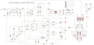 1kW smps project (based on MicrosiM design) schematic.jpg263.5 KB · Views: 699
 -
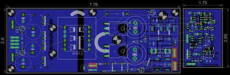 1kW smps project (based on MicrosiM design) board.jpg280.9 KB · Views: 688
 -
smps half bridge 2153 irfp460 smps plain board.pdf103.4 KB · Views: 353
-
smps half bridge 2153 irfp460 smps plain schematic.pdf35.4 KB · Views: 306
Last edited:
Stewin
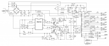
Have you thought about the delay in the protection circuit's, also I think with some small component changes you can simplify this design, the other is why the daughter card?, also use IGBT's junk the IRFP460's.The fsw is below 50kHz there are many low cost's IGBT's that can replace the 460's and the driver circuits can be simplified.Also the SG3525 can be used as a fixed frequency controller and provide higher fsw's,smaller magnetic components and has built in protection or better yet MC34025.My thought's only.I will post a design shortly.An after thought I would use a small house keeping supply for 24,12 volt supply because any short in you fan or aux circuit could cause a major failure in your main's supply.
Have you thought about the delay in the protection circuit's, also I think with some small component changes you can simplify this design, the other is why the daughter card?, also use IGBT's junk the IRFP460's.The fsw is below 50kHz there are many low cost's IGBT's that can replace the 460's and the driver circuits can be simplified.Also the SG3525 can be used as a fixed frequency controller and provide higher fsw's,smaller magnetic components and has built in protection or better yet MC34025.My thought's only.I will post a design shortly.An after thought I would use a small house keeping supply for 24,12 volt supply because any short in you fan or aux circuit could cause a major failure in your main's supply.
Last edited:
- Home
- Amplifiers
- Power Supplies
- Offline full-bridge SMPS… need help