hello all , i have an issue the smps i made heats up irfp460 or 21n50c fets but if i use irf740 the heat is not present at the fets. when i put the bulb in series with smps and load a class ab with the bulb still in series the irfp460/21n50c they do heat insanely with little load and must be mounted on the sink. but irf740 are ok when smps has little or no load.
i tried changing the gate resistors from 22ohms to 47ohms but the heating was worse so i settled on the 4.7ohms it reduced the heating a little bit but did not eliminate the heating.
but when i used irf740 the smps worked well also with a little load to the amplifier the irf740s did not overheat but warmed without a heatsink.
the smps was
- gate drive transformer is ee16 trifilliar 12turns
- gate resistors 4.7ohms
- i tried with two etd39 formers
former 1 etd39 - primary turns 23turns, secondary turns 7t - 0 - 7t aux 2turns
former 2 etd39 - primary turns 42turns, secondary turns 14t - 0 - 14t aux 4turns
both formers behaved the same regarding the heating of the irfp460/21n50c
- i used a1020 and c2655 as buffers for the gdt and 1ohm resistors .(i had used 10 ohms resistor but results were similar with 1ohm)
note the same circuit i tried using igbt an year ago but it over heated abnormally a change of gate resistor didn't help in anyway .
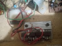
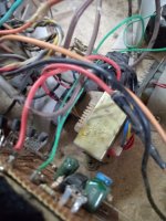
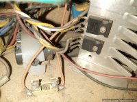
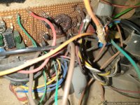
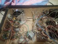
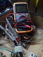
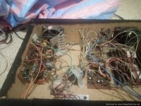
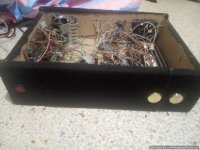
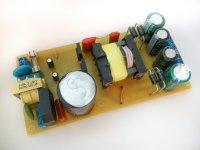
below are the pictures . kindly help out and any opinions are highly welcomed.
wow thanks buck , but seriously i don't know whether it is hard or soft switching , i have the schematic i used , and i have been making and using smps for about a decade ago
the photos and dmm measures of the smps
Offline full-bridge SMPS....need help
Offline full-bridge SMPS....need help
Offline full-bridge SMPS....need help
Hello all
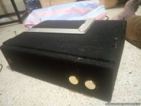
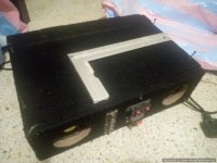
I had made for my friend an amplifier a while back (about over 8years ago) while ,I was still growing and learning about smps, also I was not conversant with pcb software and pcb etching.
He brought it to me recently to do some minor adjustment on the crossover and some little noise
I was shocked to see that
The amp was a class ab +/-30vlts and
the smps was half bridge with transfomer gatedrive ,also the smps had feedback.
The smps fets were cold (irfp460), even when I pushed the amplifier hard.
The only difference I noted was that I used bc546c and bc556c as gate drive transformer driver and the smps had feedback. That's the only change from my current smps I am working on
 it was amature done lol
but it is still working nicely
Attachments
-
 IMG_20210522_164221_302.jpg550.5 KB · Views: 187
 -
 IMG_20210522_164229_443.jpg546.8 KB · Views: 101
 -
 IMG_20210522_163722_037.jpg550.2 KB · Views: 95
 -
 IMG_20210528_182943_584.jpg382.6 KB · Views: 102
 -
 IMG_20210528_160009_901.jpg682 KB · Views: 105
 -
 IMG_20210528_155940_876.jpg788.9 KB · Views: 111
 -
 IMG_20210522_163749_400.jpg700.2 KB · Views: 171
 -
 IMG_20210528_160914_278.jpg429.1 KB · Views: 176
 -
 IMG_20210522_163745_402.jpg653.3 KB · Views: 191
 -
 IMG_20210522_163742_107.jpg627 KB · Views: 193
Last edited:
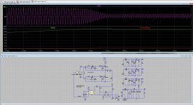
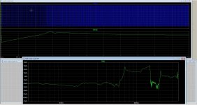
I am busy with a resonant, I have now make a model file so I can simulate it, I have software to calculate the resonant parts and that does oke.
I have proper working feedback and resonances.
Do somebody know how to find out a transformer core from a old PC supply, I have removed two, a small and bigger one looks like ETD but is not, something chinese proberly.
regards
I have proper working feedback and resonances.
Do somebody know how to find out a transformer core from a old PC supply, I have removed two, a small and bigger one looks like ETD but is not, something chinese proberly.
regards
Attachments
lolHow big smps do you want? these IGBT,s max 50 Khz or so, igbt of this size can not get that high,
are used in a welding inverter device.
Or you want a 5 kilowatt amp or so.
i want it for the smps to drive four channels of a three tier class h amp.thanks kees52 noted .
Oke, better use mosfets and resonant type supply because such low switching frequency with IGBT can disturb your amps, resonant is possiblelol
thanks kees52 noted .
with that igbt maybe then you can get some higher. For me, igbt is for welding, not audio.
thanks alot kees52 notedOke, better use mosfets and resonant type supply because such low switching frequency with IGBT can disturb your amps, resonant is possible
with that igbt maybe then you can get some higher. For me, igbt is for welding, not audio.
If you make a resonance version, then be aware the circulating current and voltage do not exceed 650 volts. So the design
is a little tricky, a much to high Q and you have easily 1000 volts over the resonance capacitor, special when startup, therefore
these resonance smps have to start delayed on a high frequency well above resonance, not below!! (capacitieve area) and all will be fine.
is a little tricky, a much to high Q and you have easily 1000 volts over the resonance capacitor, special when startup, therefore
these resonance smps have to start delayed on a high frequency well above resonance, not below!! (capacitieve area) and all will be fine.
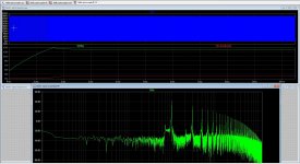
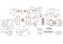
It do work, I see no feedback so it works on resonance hot spot with 470nF resonance cap. 380 volts is a little
high for 220 volt in that voltage is with a PFC here is not one, but needed with high power, it is better.
But it is build with old chips, there are better and newer ones with no need for the mosfet drive transformers.
high for 220 volt in that voltage is with a PFC here is not one, but needed with high power, it is better.
But it is build with old chips, there are better and newer ones with no need for the mosfet drive transformers.
hi all , thanks again kee2 for the explanation . i prefer gdt to chips , cause incase of failure no need
to replace expensive chips.
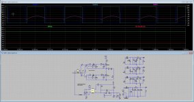
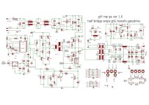
here is my updated version , just wondering whether you can draft where i can place the feedback . and also will it make this smps unstable? And is this gate drive effecient to drive fets or igbt properly?
thanking you in advance steve
to replace expensive chips.
here is my updated version , just wondering whether you can draft where i can place the feedback . and also will it make this smps unstable? And is this gate drive effecient to drive fets or igbt properly?
thanking you in advance steve
Attachments
Best is resonance in open loop set frequency about resonance in LLC configuration. Then it act as a normal transformer
on 50 hz grid without the size, softstart you always need otherwise it blows, splitted capacitor with diodes make it short circuit proof.
The schematic has not a splitter for Cr just double the capacitance and put between plus and ground, connect the transformer to the middle point
and two fast diodes over the capacitors for protection, but it can also done as on schematic.
calculatore.zip is for the feedback calculation, need to translate it because it is polish I think.
https://www.diysmps.com/forums/index.php?attachments/6-353-405-02-pdf.5404/
https://www.diysmps.com/forums/index.php?attachments/6-pdf.5403/
Now you can study a little and tool to calculate. for 1000 watts maybe a pfc is needed.
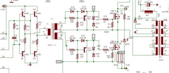
Resonance is not a easy task, maybe the schematic I have put here is usable, it has a fast feedback with a zener. The 2sk mosfets can also be others if
specs are right, min 600 volts or so. And be easy with the voltages are lethal.
regards
on 50 hz grid without the size, softstart you always need otherwise it blows, splitted capacitor with diodes make it short circuit proof.
The schematic has not a splitter for Cr just double the capacitance and put between plus and ground, connect the transformer to the middle point
and two fast diodes over the capacitors for protection, but it can also done as on schematic.
calculatore.zip is for the feedback calculation, need to translate it because it is polish I think.
https://www.diysmps.com/forums/index.php?attachments/6-353-405-02-pdf.5404/
https://www.diysmps.com/forums/index.php?attachments/6-pdf.5403/
Now you can study a little and tool to calculate. for 1000 watts maybe a pfc is needed.
Resonance is not a easy task, maybe the schematic I have put here is usable, it has a fast feedback with a zener. The 2sk mosfets can also be others if
specs are right, min 600 volts or so. And be easy with the voltages are lethal.
regards
Attachments
- Home
- Amplifiers
- Power Supplies
- Offline full-bridge SMPS… need help