What output inductors?  Seriously though, I did not put them in, as I built this one a bit before I came to appreciate all the good things an output inductor does for forward SMPSs. There are 2 spaces on the board for them, however, they are not in a position that I could couple them, so I just left them off.
Fear Not! The supply works just fine without them. One of these days, I will go back and try some vertical inductors in the circuit, and see how this affects things. Remember, though, I am dealing with FOUR outputs: +33V, -33V, +42V, and -42V, so I need to couple ALL of them together for good cross-regulaton.
Seriously though, I did not put them in, as I built this one a bit before I came to appreciate all the good things an output inductor does for forward SMPSs. There are 2 spaces on the board for them, however, they are not in a position that I could couple them, so I just left them off.Fear Not! The supply works just fine without them. One of these days, I will go back and try some vertical inductors in the circuit, and see how this affects things. Remember, though, I am dealing with FOUR outputs: +33V, -33V, +42V, and -42V, so I need to couple ALL of them together for good cross-regulaton.
Oh, the point is that such a power supply without output inductors works with peak-current control in discontinuous-mode, so it does not require precise frequency compensation, it's almost unconditionally stable since maximum phase shift from duty cycle to output is 90 degrees. The only disadvantage of using the leakage inductance of the transformer to get regulation is that sharp high current pulses are drawn from the primary side thus producing a lot of EMI and hard to filter ripple at both sides.
Adding output inductors produces a harder to stabilise second order output filter with a potentially resonant response and 180 degree phase shift, but gets rid of most ripple.
Adding output inductors produces a harder to stabilise second order output filter with a potentially resonant response and 180 degree phase shift, but gets rid of most ripple.
Very interesting point, Eva.
There is a lot of people that think that a variable duty-cycle SMPS can't work without output inductors, but the thing is that it can (I have done it), as you have pointed, they rely on the transformer inductance.
Perhaps that's what this supply is stable with no complex compensation ;-)
There is a lot of people that think that a variable duty-cycle SMPS can't work without output inductors, but the thing is that it can (I have done it), as you have pointed, they rely on the transformer inductance.
Perhaps that's what this supply is stable with no complex compensation ;-)
That's pretty much it. I can imagime that if there WERE output inductors, then the simple R||C in-band gain-limiting compensation network going from the Error amp's output to ground would be alot more involved, like a 2-pole, 2-zero filter used for current-mode forward topologies, or sometyhing like that.
Referring to one of my earlier posts in this thread, Brown's book also has a chapter on choosing and designing the compensation network, if you're unsure what type to use. I'm sure EVA would have NO problem picking the right one, even when asleep!
Anyhow, Eva is exactly right- the supply is VERY stable thoughout its load and input ranges.
N-Channel,
I think Eva was not referring to regulation when she said that the supply must be unconditionally estable She was refering to the fact that the maximum phase shift never reaches 180º with no output inductors, so the possibility of oscillation is zero at any frequency.
That's opposed to conditional estability. A so called system has a phase response that reaches or surpasses 180º at some point, even if the gain is below 0dB at that frequencies. But a variation in its working conditions, such as low load/line can make it unstable.
Then there are inestable systems, that will oscillate under all circunstances as the phase margin is 0 or less.
Best regards,
Pierre
I think Eva was not referring to regulation when she said that the supply must be unconditionally estable
She was refering to the fact that the maximum phase shift never reaches 180º with no output inductors, so the possibility of oscillation is zero at any frequency.That's opposed to conditional estability. A so called system has a phase response that reaches or surpasses 180º at some point, even if the gain is below 0dB at that frequencies. But a variation in its working conditions, such as low load/line can make it unstable.
Then there are inestable systems, that will oscillate under all circunstances as the phase margin is 0 or less.
Best regards,
Pierre
I've been just repairing and testing an old 4 channel Alpine V12 amplifier that uses that "inductorless" regulated power supply topology.
It actually uses a pi filter, made out of two small 470uF 35V capacitors placed inmediately after the diodes, two pot-core inductors, and two big 6800uF 35V capacitors. The first pair of small capacitors heat up badly even when only two channels are driving a speaker load at high volumes. Furthermore, the two 3300uF 16V ripple smoothing capacitors from the primay side also heat up badly. Note that all them are low ESR types, yet after some time they get hot enough to be uncomfortable to the touch.
And that is what happens with only two channels driven, the cover removed and approx 16ºC ambient temperature. Now figure out what temperature will the cases of that poor capacitors reach when the amplifier is mounted inside a car and all channels are driven.
It's quite a flawed topology, I never liked it.
And that's an ALPINE... I don't want to think what happens with a JBL or a Pioneer one ;-)
EVA, if that SMPS is let run unregulated (almost full duty cycle), could it work much better (less stress on the capacitors for a start)? (if the output voltage is allowable, of course)
The thing is that almost every car amp I have seen has no or little output inductor (a 1-5uH choke in the bests cases), but I think it is not a problem if duty cycle is very high. Am I right?
It depends on transformer turns ratio and target output voltage adjustment. I would arrange such a power supply so that the regulation only works as an output voltage limiting approach. That would cause full duty cycle operation and little ripple for input voltages less than, lets say, 13V. And the PSU from that amplifier was working much in that way, keeping internal rails below +-28V.
During the test I was powering the amplifier through two meters (1 meter cord) of 1mm^2 wire to intentionally produce some voltage drop, since my 120A power supply is currently adjusted for a fixed 14.5V output and I feel too lazy to stick a potentiometer in it (I have a very useful one for current limit, though). These working conditions are not much different from the ones present in a car with a 14.4V regulator and the engine turned on, since the voltage was dropping to 12V or less during transients, where gate-drive waveforms showed that the PSU was efectively swinging to full duty cycle.
I think that this long piece of 1mm^2 power wire was the only reason for those poor 470uF 35V capacitors not to explode, powering it from 14.5V or 15V without any voltage drop would have been quite insane (then again, I was asked to repair the amplifier, not to destroy it further...).
Concerning modern JBLs or Pioneers sold in big stores, don't expect any supply regulation from them. Old Pioneers sold 10 years ago employed true regulation, with non-coupled output inductors as their only flaw, though.
During the test I was powering the amplifier through two meters (1 meter cord) of 1mm^2 wire to intentionally produce some voltage drop, since my 120A power supply is currently adjusted for a fixed 14.5V output and I feel too lazy to stick a potentiometer in it (I have a very useful one for current limit, though). These working conditions are not much different from the ones present in a car with a 14.4V regulator and the engine turned on, since the voltage was dropping to 12V or less during transients, where gate-drive waveforms showed that the PSU was efectively swinging to full duty cycle.
I think that this long piece of 1mm^2 power wire was the only reason for those poor 470uF 35V capacitors not to explode, powering it from 14.5V or 15V without any voltage drop would have been quite insane (then again, I was asked to repair the amplifier, not to destroy it further...
).Concerning modern JBLs or Pioneers sold in big stores, don't expect any supply regulation from them. Old Pioneers sold 10 years ago employed true regulation, with non-coupled output inductors as their only flaw, though.
Alpine Retrofit
EVA-
I know Alpine likes to cram alot into a little space, but is there enough real estate in there that you could retrofit a coupled unductor before the 470mF caps? It would be interesting to see how this would affect those caps' temperatures AND the supply's response to changing lines and loads. What type of compensation network is used?
I'm suprised that the PSUs in the V12s aren't better designed- the V12s were supposed to be their better line of amps (Regulated PWM, noise-free, blah, blah, blah).
I have several 3522Ss (2x30W) amps (older models), and don't remember seeing any coupled inductors on the output side before the first filter caps. I think there are a pair of non-coupled indies on between the "banks" of capacitors, though. Of course, there were Alpine's "entry" level series of amps then. They do work fine for my applications, though If I ever attempt to do a car amp again, that's not a design I would follow.
It's too late, the amplifier has been already delivered to the customer.
Compensation looked like a pole in the origin (actually determined by TL494 op-amp open loop gain) and a zero somewhere. An easier approach would have been to remove those 470uF 35V capacitors and leave the diodes driving the two pot inductors, but it would have probably oscillated and suffered from asymmetric rails. I don't know how they were sensing output voltage, but there were no optocouplers so it was done directly. I think that 12V ground and speaker ground were joined, and balanced inputs employed, something common in old amplifiers and seldom seen in current ones, though.
I would have played a bit with the circuit if the amplifier was mine, but it wasn't. There was not enough space for a suitable coupled inductor anyway, but the PSU would have just turned into a classic transformer coupled buck converter if one was connected and suitable compensation was applied.
Also, last week I repaired a Steg rated at 2x225Wrms@4 ohms and 730Wrms bridged. Its power supply was blown, so I had to investigate how it worked anyway. Interestingly, it was a true transformer-coupled buck converter with a big coupled output inductor made with two stacked iron powder cores. However, regulation wasn't closed loop, instead, the duty cycle was simply adjusted proportionally to the voltage present in the 12V bus, thus yielding only partial but effective regulation.
Main transformer turns ratio was 19:4 and internal rail voltage when idle was +-48V with 14.5V input, but still +-45V with just 11V input. I tested it in bridge mode at full output swing with music signals and 14.5V input for a short period of time, and internal rails just dropped to +-43V (figure out the amount of power). The load was a poor 4 ohm 15" driver.
Why did that poor power supply blew? Well, take 80V effective output swing, divide it by 4 ohms and you get 20A drawn during transients in worst case. And 20A drawn from each rail causes (20+20)*19/4 = 190A peak to flow in the primary side, that were switched with just two banks of three old STP60N06 each (all fried), driven from 39 ohm gate resistors (too big!) and featuring something like 0.018 ohms Rds-on. I replaced them by HUF75344P3, driven from 10 ohm gate resistors and featuring only 0.007 ohms Rds-on, hoping that the lower conduction losses, and switching losses due to faster drive, could contribute to make that thing more reliable. Also, the owner of that car has been using the amplifier with a weak battery for months, so input voltage has been probably 11V most of the time (yielding high currents during full duty cycle), this explains a lot...
If the controller is in the secondary side (in offline or DC/DC converters), no optocoupler is needed and everything is easier. That happens, for example, with A&T Labs K6 supply.
However, I didn't want to put the controller in the secondary, as I have a startup circuitry directly from the rectified mains. Once the circuit starts, it is self-fed by an aux. winding in the transformer, rectified and followed by a 7815 regulator. From then on, the only power consumption from the startup is a zener biasing (around 1W dissipated in three series connected resistors). That's why I need it to be in the primary side.
So my only solution is using an optocoupler unless I feed the control circuitry with a small 50Hz transformer (that I really don't want) and move it to the secondary, but I think my solution is much ellegant.
This afternoon or tomorrow I will first try to substitute the Coilcraft GDT transformer with another from Pulse. If it works better, I will go back to 80KHz (now it runs at 40KHz) and I will concentrate in the feedback loop again. I will tell you how it goes...
EVA-
Too bad! Looking at several of the Alpine Amps I have cracked open, and, looking at the service manuals I have ordered from Pacific Coast Parts, I see that the TL494 is run essentially wide open, max duty cycle of 45-50% per output. There is no sensing from the output voltage(s). As I read the schematic, I think the compensation network is pole-zero.
The only Alpine amp I have ever heard of having truly isolated input and output grounds with optoisolator monitoring was the 3558 class A amp. 40W x 4 into 4W, and I don't remember the S/N, THD, or other numbers.
I didn't know Alpine was using balanced inputs. I thought only Adcom (their now-defunct car audio division) was using them. Hmmm.....
Wow on the N-Channel MOSFETs in the Steg. Amazing how a little simple math can debunk all those inflated numbers! Even if it were a true 225W, sizing the MOSFETs the way the manufacturer did is not good engineering practice.
Pierre-
I agree with you in wanting to keep the control on the primary side of the supply. Keeps thing simpler, and the use of an optoisolator doesn't add too much complexity to the circuit. Also allows the use of high-and-low side MOSFET driver ICs, like the IR 2110-series of chips, instead of driver transformers. However, Driver ICs -v- transformers, each has their advantages and disadvantages.
Having the controller on the primary side also allow for the possibility of the input voltage to be a high-voltage DC. Not that anyone would ever run into commercially-available high-voltage DC, but you never know what you will come across.
Let us know how the new test goes.......
Steve
Driver Transformers
Pierre,
Thought of something else- Coilcraft (Chicago, Il) makes ready-made driver transformers for half-bridge topologies (use two for full-bridge). I got a couple a few years ago for my voltage-mode SG3525-based half-bridge ps for audio apps., and they worked GREAT! Nice, clean switching waveforms.
I know this IS a DIY website, but if you want to avoid the added headache of having to designing them, then these ready-made little goodies might do the trick!
Just a thought.
Steve
I assume you mean gate drive transformers, SD250 series, right?
In fact my supply is running with one of them (SD250-4)!, but I am not very happy with it, the sw. waveforms are not too good. Please have a look at my other thread (assymmetric outputs in half-bridge), you can even see some photos. Perhaps you can suggest something...
It is curious, they should work OK, as the EV rating is theoretically high enough!
In order to put it to work with not too high losses I had to reduce sw. freq. from 80KHz to 40KHz. (the rise/fall times are too slow).
I have ordered a couple of samples from Pulse, I want to try with them. They are also smaller.
SD250-4s
Pierre,
Yes they are the 250-4s. There hase a 1:1.5:1.5 winding ratio, but I uaed the 250-3s, with a 1:1:1 ratio. I was working at the time with a 15VDC supply to the '3525, and I didn't want to overshoot the 20Vgs rating of the MOSFETs, and possibly blow them. 15VDC x 1.5 = 22.5VDC not good.
I will look at the other thread and see if I can come up with any ideas.
Steve
Pierre,
Yes they are the 250-4s. There hase a 1:1.5:1.5 winding ratio, but I uaed the 250-3s, with a 1:1:1 ratio. I was working at the time with a 15VDC supply to the '3525, and I didn't want to overshoot the 20Vgs rating of the MOSFETs, and possibly blow them. 15VDC x 1.5 = 22.5VDC
not good.I will look at the other thread and see if I can come up with any ideas.
Steve
After the weekend, I have only been able to test the supply as it is now (at 40KHz with the Coilcraft transformer), with real amplifiers and under real music load.
My transformer has 26 primary turns, yielding around 1100 Gauss peak flux density at 80KHz, but about 2200 at 40KHz, that is too high.
The only component that has been heating up a bit after some pushing is the transformer itself. Can it be due to excessive flux?
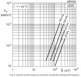
Following the 3C90 graphs, the thing is that running at 50KHz/2000 Gauss produces about 3 times greater power losses than running at 100KHz/1000 gauss, so I assume that running at 80KHz with 1100 gauss should reduce transformer heating very noticeably, am I rignt?
In every other aspect, it works excellent! No noise in the amplifiers and almost no interference in a test FM radio.
Best regards,
Pierre
My transformer has 26 primary turns, yielding around 1100 Gauss peak flux density at 80KHz, but about 2200 at 40KHz, that is too high.
The only component that has been heating up a bit after some pushing is the transformer itself. Can it be due to excessive flux?
Following the 3C90 graphs, the thing is that running at 50KHz/2000 Gauss produces about 3 times greater power losses than running at 100KHz/1000 gauss, so I assume that running at 80KHz with 1100 gauss should reduce transformer heating very noticeably, am I rignt?
In every other aspect, it works excellent! No noise in the amplifiers and almost no interference in a test FM radio.
Best regards,
Pierre
I'm not aware of such core heating issues. In my 120A power supply the E42 cores of N27 (low frequency) marerial are routinely driven to a bit more than 300 mT (3000 gauss) at 32Khz, and they get just slightly warm, not enough to be discomfortable to the touch. Under transient conditions the flux may even reach 450mT, but I've seen no more traces of core saturation since I got the current sensing and control stuff right and I found the way to achieve a symmetrical layout.
Note that high frequency ringing causes a lot of dissipation in ferrite cores, particularly in low-cost low-frequency materials such as N27, but I got rid of almost all the ringing.
Note that high frequency ringing causes a lot of dissipation in ferrite cores, particularly in low-cost low-frequency materials such as N27, but I got rid of almost all the ringing.
My core is 3C90 grade, not a very high frequency one of course.
Are you suggesting that leakage inductance causing ringing can be the culprit?
When I speak about heat, I mean that it reachs around 25ºC above ambient (DS1820 sensor placed between lateral ferrite and the windings) after half an hour or so, with 2x150W peak music load. Not very worrying but I would like to extract far more power from it.
This is the graph I referred to. Marked are the two referred points of operation: 40KHz/2200G and 80KHz/1100G.
Losses from the material are about 3 times lower at the higher frequency (1.2W versus 3.5W aprox with ETD44).
As the transformer is the same, _its_ temperature should go noticeably lower, am I right? (ok, mosfets will be hotter unless I fix the low rise time problem).
Best regards,
Pierre
Losses from the material are about 3 times lower at the higher frequency (1.2W versus 3.5W aprox with ETD44).
As the transformer is the same, _its_ temperature should go noticeably lower, am I right? (ok, mosfets will be hotter unless I fix the low rise time problem).
Best regards,
Pierre
Attachments
My calculations are wrong, divide the previously mentioned flux densities by two. I was not taking into account that I'm using two primaries connected in series. This makes me consider going for a lower switching frequency (30Khz), and three turn secondaries for a bit more than 200mT instead of four turns for a bit more than 150mT.
Core losses seem to increase with the flux density squared and also seem to increase proportionally to the inverse of the frequency. You may try to find a compromise between 40Khz and 80Khz, lets say 56Khz. That would reduce core losses without doubling the switching losses.
Anyway, note that your 3C90 ferrite suffers the lowest losses at 100ºC and is good up to 200ºC, so 50ºC or 60ºC operation shouldn't be a problem. On the other hand, switching devices are not so happy at 100ºC.
- Status
- This old topic is closed. If you want to reopen this topic, contact a moderator using the "Report Post" button.
- Home
- Amplifiers
- Power Supplies
- SMPS control loop estability