Hi
My friend designed two regulator with very small size. He is willing to offer PCB sample to member on diyaudio forum.
Dual regulator : SIZE: 82mm X 59mm
Positive regulator : SIZE: 65mm X 41mm
Supply voltage range : 5V -- 80V
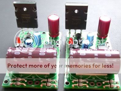
here are the pics of the regulators:
dual
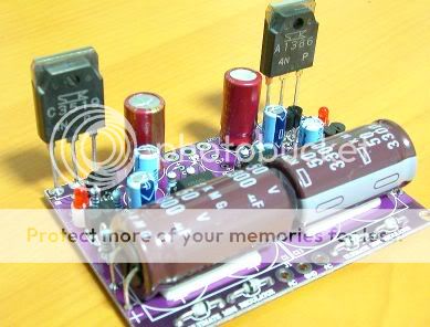
positive
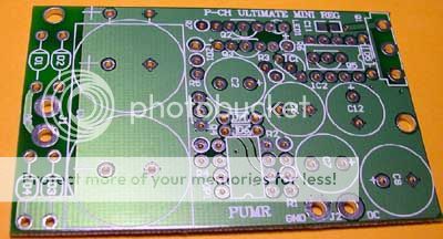
This is the PCB:
dual
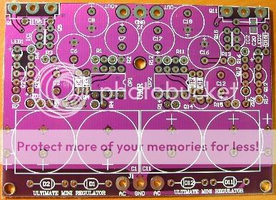
positive
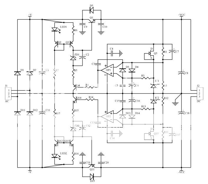
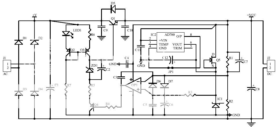
Schematic:
dual
positive
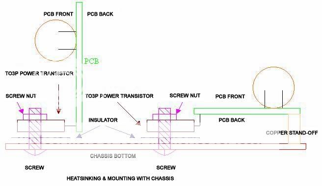
The mounting on chassis:
each member from DIYAUDIO can ask for one sample PCB(dual or positive). Because the different voltage has different BOM, please tell me output voltage you need. Only 20pcs of samples for each reg.
Applyer only pays the registered airmail shipping fee 3.00USD.
My email address: coffin@diyzone.net
cheers
Coffin
My friend designed two regulator with very small size. He is willing to offer PCB sample to member on diyaudio forum.
Dual regulator : SIZE: 82mm X 59mm
Positive regulator : SIZE: 65mm X 41mm
Supply voltage range : 5V -- 80V
here are the pics of the regulators:
dual
positive
This is the PCB:
dual
positive
Schematic:
dual
positive
The mounting on chassis:
each member from DIYAUDIO can ask for one sample PCB(dual or positive). Because the different voltage has different BOM, please tell me output voltage you need. Only 20pcs of samples for each reg.
Applyer only pays the registered airmail shipping fee 3.00USD.
My email address: coffin@diyzone.net
cheers
Coffin

amplifierguru said:Maaate - thought your luck had changed!
Sorry to say it looks like a nut to me.
cheers,
greg
Yeah, I was getting a bit excited, sorry, I'm not interested in nuts.
")
hey Coffin,
I was only having a little joke, it is perfectly clear that a female screw is a nut. Sorry, I should have been a little more respectful.
Hi
The performance of the PCB is pretty good!
Very low noise, low impedance.
The sound is very neutral and transparent.
Actually, the dual mini reg PCB now is the second version(the first version is color green, 2nd is purple), it sells very hot in Taiwan and HongKong.
cheers
Coffin
The performance of the PCB is pretty good!
Very low noise, low impedance.
The sound is very neutral and transparent.
Actually, the dual mini reg PCB now is the second version(the first version is color green, 2nd is purple), it sells very hot in Taiwan and HongKong.
cheers
Coffin
Hi
the english instruction and BOM are on!
http://circulator.bravehost.com/minireg.htm
cheers
Coffin
the english instruction and BOM are on!
http://circulator.bravehost.com/minireg.htm
cheers
Coffin
I have examined the pcb's and so far I'll notice this:
The vias are pretty small. I'll think the inductance will be a but less with bigger holes, may not be critical here
Power traces are a bit thin because there are not short circuit protection.
The C9, C10 should be in place I'll think but C10 and C19 are totally unnecessary. The regulator will most likely oscillate.
The pcb has a whole groundplane and I'll think it would be wise to at least make some "ditches" to lead currents away from the opamp and the other sensitive parts.
The fastest opamp in the partslist is OPA637 and I don't know if fast won't work, like the AD825, but it might.
Despite my remarks, excellent looking pcb's. , the same quality feeling as my pcb's
The vias are pretty small. I'll think the inductance will be a but less with bigger holes, may not be critical here
Power traces are a bit thin because there are not short circuit protection.
The C9, C10 should be in place I'll think but C10 and C19 are totally unnecessary. The regulator will most likely oscillate.
The pcb has a whole groundplane and I'll think it would be wise to at least make some "ditches" to lead currents away from the opamp and the other sensitive parts.
The fastest opamp in the partslist is OPA637 and I don't know if fast won't work, like the AD825, but it might.
Despite my remarks, excellent looking pcb's.
, the same quality feeling as my pcb's Banned
Joined 2002
I ment C19 and C20 are not necessary.peranders said:The C9, C10 should be in place I'll think but C10 and C19 are totally unnecessary. The regulator will most likely oscillate.
The pcb's are really small, smallest so far but the price for this is standing parts and SMD parts on the solderside, not so productionfriendly.
jleaman, if you look here you'll see my complete dual supply super unit with transformer and everything.
This may be a problem or not. It depends on the pcb and used opampsdarkfenriz said:Op-amps supplied directly from output regulated voltage?
It's correct, just check Jung's/Didden's articles.darkfenriz said:Q4/Q14 surely not swaped.
Q4 is an emitter follower from the opamp if you don't realize it.
peranders said:
I ment C19 and C20 are not necessary.
Wrong again.
C9, C19 OK
C10, C20 not OK
- Status
- This old topic is closed. If you want to reopen this topic, contact a moderator using the "Report Post" button.
- Home
- Amplifiers
- Power Supplies
- Mmini regulator (sample offering)