I have been, at last, able to regulate my PSU.
The control setup is as follows:
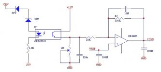
- Secondary: two 30V zeners, 1k5 resistor and optocoupler diode in series, from + rail to - rail.
- Primary control: optocoupler phototransistor has collector to +12V (control IC supply), emitter with adj. resistor to GND (filtered with a 120nF cap as I found it very noisy)
- Internal SG3525 Error opamp configuration: Error signal is taken from phototransistor emitter, fed to the error opamp inverting input via a 10K resistor. From there, 330K resistor in parallel with 10nF, to COMP pin (inverting amplifier with gain 33).
The non-inverting input is tied to Vref (5.1V)
COMP pin has about 500nF to GND.
The supply regulates OK, but with "light" loads (light being 100W), it shows some strange periodic oscillation, about 30Hz, 4Vpp (amplitude and freq. varying as load changes).
It is as it the control was not very estable. I am also afraid that with those values its transient response will be veeery slow.
How can I find the optimum values for both (almost)no load good behaviour and adequate transient response?
The supply is running at 40KHz by the moment. Max power I have tested is 450W for several seconds.
Best regards,
Pierre
The control setup is as follows:
- Secondary: two 30V zeners, 1k5 resistor and optocoupler diode in series, from + rail to - rail.
- Primary control: optocoupler phototransistor has collector to +12V (control IC supply), emitter with adj. resistor to GND (filtered with a 120nF cap as I found it very noisy)
- Internal SG3525 Error opamp configuration: Error signal is taken from phototransistor emitter, fed to the error opamp inverting input via a 10K resistor. From there, 330K resistor in parallel with 10nF, to COMP pin (inverting amplifier with gain 33).
The non-inverting input is tied to Vref (5.1V)
COMP pin has about 500nF to GND.
The supply regulates OK, but with "light" loads (light being 100W), it shows some strange periodic oscillation, about 30Hz, 4Vpp (amplitude and freq. varying as load changes).
It is as it the control was not very estable. I am also afraid that with those values its transient response will be veeery slow.
How can I find the optimum values for both (almost)no load good behaviour and adequate transient response?
The supply is running at 40KHz by the moment. Max power I have tested is 450W for several seconds.
Best regards,
Pierre
Attachments
Well, of course, from unit to unit there would be an error due to zener tolerances, but once it is adjusted (there is a potentiometer), the output should be reasonably estable (without having into account temperature effects on the zeners, optocoupler and references, of course).
But that should be more than enough, anyway.
The problem is that it tends to "oscillate", and I have found that not only at light loads. What changes with load is the frequency of that oscillation. Its amplitude is around 4Vpp.
Best regards
But that should be more than enough, anyway.
The problem is that it tends to "oscillate", and I have found that not only at light loads. What changes with load is the frequency of that oscillation. Its amplitude is around 4Vpp.
Best regards
Why don't you wire the error amp in the way I told you? That 120nF capacitor is ruining stability, there must be only a single LF pole provided by the output filter and compensated by a zero in the error amplifier, and the optocoupler is probably too slow to keep the required phase margin at high frequencies when compensation is not applied in the photodiode side.
Thanks for the comments.
Sorry Eva, what was your suggestion: using an external opamp and keep the SG3525 internal error amplifier as a non-inverting unity gain buffer?
I added the 120nF capacitor at the start, in open loop (when I regulated the output by means of a potentiometer), because when I observed the emitter waveform it was pulsing at the switching frequency, when I expected DC (with noise) with estable dummy load and input voltage, so I added it as a lowpass filter.
Now it comes to my mind that perhaps it was due to noise pickup by the scope probes...
I will try to remove it and see what happens.
Given that my LC filter is 47uH + 6600uF per rail, what freq. should I place a zero in my fb loop at?
Thanks!
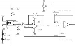
After a little more experimenting, I have decided to follow Eva's advice and add an external opamp for the error amplifier.
My PSU regulates about ok, but there is a low frequency ripple (around 5-6Vpp) with low loads, which produces a very audible sound on the amplifier. I guess it is not estable.
Please tell me if the following sch is a good starting point. The error amp must be compensated, but first let's concentrate on the DC configuration:
thanks!!!
Attachments
- Status
- This old topic is closed. If you want to reopen this topic, contact a moderator using the "Report Post" button.