...another brick in the wall.... in the wall of Choco's Sub Woofer Story..
Encouraged by good support here, I decided really to set up
a SMPS for my sub. The SMPS will consist by a PFC boost converter followed by a forward halfbridge converter.
Typically such boost converters need a DC rail capacitor, which draws a heavy current peak during turn ON.
In my design this cap will be around 150uF and can already cause
a current peak around 140 A. My trials with 330uF even showed 180A
and flickering of my room.
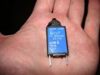
I found that bimetal overcurrent protectors seem to be able to handle this quite well.
Any experiences with such bimetal overcurrent protector fuses are welcome.
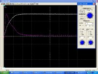
The attached screen shot shows the current pulse and charging of
the 165uF rail capacitor in worst case.
White trace: DC rail, 100V/div.
Colored trace: Charging current, 50A/div.
Encouraged by good support here, I decided really to set up
a SMPS for my sub. The SMPS will consist by a PFC boost converter followed by a forward halfbridge converter.
Typically such boost converters need a DC rail capacitor, which draws a heavy current peak during turn ON.
In my design this cap will be around 150uF and can already cause
a current peak around 140 A. My trials with 330uF even showed 180A
and flickering of my room.
I found that bimetal overcurrent protectors seem to be able to handle this quite well.
Any experiences with such bimetal overcurrent protector fuses are welcome.
The attached screen shot shows the current pulse and charging of
the 165uF rail capacitor in worst case.
White trace: DC rail, 100V/div.
Colored trace: Charging current, 50A/div.
Attachments
....well, at least nobody is crying: "Big NoNo! "
I forgot to explain why I am not planning to use a standard
glass fuse. I want to go for a safety class II design, without earth.
The related 2-pin mains connectors (like laptop SMPS etc.) are rated for 2.5A only. I don't trust a 2.5A glass fuse to charge 165µF/450V caps without inrush current limiter. Also these exchangeable fuses typically are replaced by somebody, without taking care about the proper rating....
After I found that these 2A bimetal overcurrent protections are able to handle the current peak quite easy.... I got a little bit concerned if they would trip reliably in case of an overcurrent.
But they do fine. When running them with 2.5A, they trip after 4 minutes.
I've used these bimetal switches for speaker protection applications. They are very effective in limiting RMS current while allowing for a high peak to average ratio. However, they seem slower than a conventional fuse during a short circuit and they are not going to help to reduce the inrush current peak so you may also need something like a NTC surge limiter.
I'm considering a thyristor controlled soft-start and power on/off circuit for my applications since I feel NTC surge limiters are not well suited for more than 1KW. It would be achieved by replacing two of the diodes of the main bridge by thyristors.
I'm considering a thyristor controlled soft-start and power on/off circuit for my applications since I feel NTC surge limiters are not well suited for more than 1KW. It would be achieved by replacing two of the diodes of the main bridge by thyristors.
Eva said:I've used these bimetal switches for speaker protection applications. They are very effective in limiting RMS current while allowing for a high peak to average ratio. However, they seem slower than a conventional fuse during a short circuit and they are not going to help to reduce the inrush current peak so you may also need something like a NTC surge limiter.
I'm considering a thyristor controlled soft-start and power on/off circuit for my applications since I feel NTC surge limiters are not well suited for more than 1KW. It would be achieved by replacing two of the diodes of the main bridge by thyristors.
The very slow tripping behaviour is matching to my own observation. And this exactly is my intension, I needed a fuse that can handle the inrush currents and still providing to trip at a rated current of 2.5A or less.
I was also considering a inrush current limiter, but...
.... the simpler, the better...
There is one point, which makes me little bit thinking.
The short circuit protection, there is no limitation and in theoretical worst case some hundred A will happen and then this bimetal has to break it. Do such bimetal switches offer good "high breaking" properties? Or would I need a traditional sand filled glass fuse rated for 10A (so that it does not trip due to the current peak)....
Thanks for bringing the NTC back to my mind. I never tried it up to now. But it could be the most simple way to avoid the inrush current peak....
Thyristor inrush current limiter:
...so you are planning to limit the current on the DC side, right?
A thyristor should provide fine properties, high current capabilty combined with high voltage properties.
Up to now, I only used the most traditional current limiter circuit:
A series resistor, which is short circuited by a relay after a short delay. Not smart. But simple and bullet proof.
I have some respect regarding any electronic switch that runs without any voltage clamping at the mains.
Sometimes there are quite massive pulses on the mains, which easily blow even 1kV devices... So I decided not to enter this struggle, even after considering that a current limiter switch is usually turned ON and with this clamps itself... of course I could add some overvoltage clamping device behind the EMI filter...
.... hm, sounds like worst case considerations are 'killing my softly'...
Damn, you are even more demanding on the performance of your circuits than me (even knowing that I'm switching nearly 2KW with just four TO-220 bipolar devices and less than 40W losses).
Concerning NTC surge limiters, I've seen them used in almost every piece of equipment that has to rectify mains voltage. Also, your power range is not too high to prevent their usage, so you should consider them.
Concerning my thyristor based system, it's driven by a PIC12C (the cheapest one) and produces a firing angle sweep, altough it's far from finished. I've simulated mains transients (plugging and unplugging stuff) and the worst thing that can happen is parasitistic turn-on of one of the thyristors. Such a complex soft-start circuit is not worth the expense for a low power application, but for a 2KW unit with 2000uF on the mains side it seems reasonable to me.
Eva said:Damn, you are even more demanding on the performance of your circuits than me (even knowing that I'm switching nearly 2KW with just four TO-220 bipolar devices and less than 40W losses).
Hi SMPS Queen!
... guess you are wrong in this regard.

I'm just a reliability junky. Nothing frustrates me more than having finished something, which starts to require lot's of maintainance or makes me afraid of using it...
I care less about 'high tech inside'
and I don't mind about 'ugly inside'.
Eva said:
Concerning my thyristor based system, it's driven by a PIC12C (the cheapest one) and produces a firing angle sweep, altough it's far from finished.
µC controlled... perfectly suited to impress a digital greenhorn like me !
'...firing angle sweep...'
Now I am estimating that you are not working on the DC side,
but sounds more like you are integrating the thyristors into your rectifier...
Two diodes & two thyristors?
Eva said:
I've simulated mains transients (plugging and unplugging stuff) and the worst thing that can happen is parasitistic turn-on of one of the thyristors. Such a complex soft-start circuit is not worth the expense for a low power application, but for a 2KW unit with 2000uF on the mains side it seems reasonable to me.
Not bad !
Even if you will probably cause mainly symmetric disturbance (L vs. N) and less asymetric disturbance (L&N vs. Earth), such plugging tests should give you a good impression about real life conditions.
I guess you also plugged / unplugged such unpleasent stuff as
electrical heaters with inductive heating wires.., heavy & unloaded transformers,..... some kV-precharged capacitors... etc...
How about welding equipment?

I guess some real stuff is even better than standardised test equipment...
Hm, frankly speaking...
Up to now, I did not plan to test my boost converter like this!

- Status
- This old topic is closed. If you want to reopen this topic, contact a moderator using the "Report Post" button.
- Home
- Amplifiers
- Power Supplies
- Fusing my Boost Converter