Hi Guys and Ladies!
Somehow I am not getting lucky with my PSU concept for my subs.
I planned to design a SMPS which would allow universal AC input and additional 12V car battery supply.
The part which makes me thinking is the line SMPS.
First I planned a PFC-Boost + Halfbridge Forward Converter.
With my lower power requirements (600W max. / 150W average), I started thinking about an Flyback, which would allow a simple single stage design.
BUT :
No matter which topology I choose there are several drawbacks already in theory.
-The safety standard EN 60065 (Table 11) would require enormous creepage distances for reinforced isolation. Safety class II is a must for me as I do not want to have a mandatory earth connection.
In case of a flyback I would end up in a minimum creepage of
12.6mm and in case of PFC-Boost + Halfbridge around 10mm.
...values which make a suitful small sized transformer difficult...
The leakage inductance for the flyback is critical anyway.
BTW: I found some cut core material, which can handle high
flux and HF operation (pic...).
-EMI filtering:
a) I would need massive X-Filtering.
b) To avoid HF-noise on audio signal ground, there would probably the need of screening layers in the trafo in order to catch the capacitive leaking currents from the fast switched high voltages.
Size and weight of all this will be at least the same like a 250VA torroid.
I will need large caps ( 2F ) for the 12V battery supply anyway.
Coming from this it looks quite reasonable to use a simple 120V/240V ==> 10V torroid and a rectifyer instead of all the trouble above.
2F caps will lead to an acceptable low rippled 12V supply and
a traditional regulated push pull SMPS should then give stable
+/- 50V rails for the amp itself (or any other desired voltage).
So in my application the only remaining advantage of the
line-SMPS seems to be the possibility to draw sinusodial currents from the mains.... hm, who cares at such low power !!
What do you think?
Attachments
Don't let outrageous safety regulations pi$$ you off. They were written just for that purpose, in order to help big companies to monopolize SMPS development (and EMC actually states for 'Eliminate Minor Competitors').
Have you ever seen a 50Hz standard toroid with three layers of mylar tape between primary and secondary windings? or even with a faraday shield? No! Most of them use a single layer of a low quality non-adhesive tape with some overlapping, that melts at approx 90ºC. Furthermore, they suffer from high primary to secondary leakage currents due to thin insulation and huge capacitance, so earthing is always required. They don't met any leakage specification, most brand-new big toroids will shock you if you touch any wire from the 'isolated' secondary windings with your feet wet on the floor.
Have you ever seen a 50Hz 'EI' transformer witn 16mm or 10mm primary to secondary creepages? No! They use no creepages at all!
Everybody is using these 50Hz transformers without trouble and nobody is messing with their manufacturers.
I hope you got what I'm trying to explain.
PD: I use just 5mm creepages (2.5mm per layer) and some plastic tubing for my SMPS transformers, and this already makes them *far safer* than most 50Hz ones. Earthing is a must anyway.
Hi Eva!
Thanks for the clear words. And I believe that there are
many 50Hz trafos out in the field that have poor isolation, even
if you pick a certified one.
Sometimes it seems to be sufficient that the trafo just passes the
4kV isolation test, to get a safety certification.
I only wound off one E-core-trafo, 15 years back. And that one had triple isolation layers between primary and secondary. The creepages would have been to small from what I would expect, even when I take into account that for a 230V standard transformer 5mm should be sufficient. But that transformer also had a shielding layer to be connected to ground and with this I expect that basis isolation would do in that particular case and so half of the creepage would be OK.
The inconvinient high requirements for the creepage in my SMPS are resulting from the fact that the RMS and/or DC values (that's the criteria according EN60065) in my boost converter would be 480V compared to 230V in a standard 50Hz torroid....
With regard to EMI, I feel that a shielding layer in a 50Hz trafo is less important than in a SMPS. The SMPS has high voltages and excessive du/dt typically ranging between 100V/µs .... 10kV/µs, while a 50Hz trafo operates with 0.1V/µs .
Do you really always ground all components?
One of the earliest reasons for humm that I discovered were ground
loops between the power plug and antenna...
In the beginning I simply decoupled the antenna shield.
Since some years I decided to change to class II designs for my DIY projects... ...and up to now I am quite lucky with that...
Many HiFi manufacturers have done this step, too.
Just N & L at the mains plug, no earth.
Danko, I guess your question is also answered above.
For my shieldings I planned a pseudo EMI-earth formed by
two Y-caps between L&N. The center tap of these both
would have been connected to the shielding. Shielding
would be inside the SMPS trafo, between primary & secondary.
And around the entire SMPS unit .
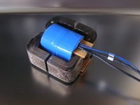
Attached a picture of my first winding trial for the flyback solution. 6mm margin tape on each side ==> with the additional
thickness of the isolation between prim/sec, I would get around
13mm creepage... The wires are isolated with a shrinking sleeve, which gives 0.6mm isolating wall thickness.
This design did not have interleafed prim/sec and the leakage
inductance was around 7µH. Not funny if you go for a flyback with
20A peak in case of 120V/AC.....
Even with interleafed construction, I guess still half of it will remain.
And I would have to consider the inductance of the rectifier loop on the secondary. Let's guess around 10nH, resulting on reflected 2µH on the primary side (Trafo: 15 turns : 1 turn).
BTW:
Now I am between the seats. Yesterday I was tending more
to the simple way.
Now ....
Thanks for the clear words. And I believe that there are
many 50Hz trafos out in the field that have poor isolation, even
if you pick a certified one.
Sometimes it seems to be sufficient that the trafo just passes the
4kV isolation test, to get a safety certification.
I only wound off one E-core-trafo, 15 years back. And that one had triple isolation layers between primary and secondary. The creepages would have been to small from what I would expect, even when I take into account that for a 230V standard transformer 5mm should be sufficient. But that transformer also had a shielding layer to be connected to ground and with this I expect that basis isolation would do in that particular case and so half of the creepage would be OK.
The inconvinient high requirements for the creepage in my SMPS are resulting from the fact that the RMS and/or DC values (that's the criteria according EN60065) in my boost converter would be 480V compared to 230V in a standard 50Hz torroid....
With regard to EMI, I feel that a shielding layer in a 50Hz trafo is less important than in a SMPS. The SMPS has high voltages and excessive du/dt typically ranging between 100V/µs .... 10kV/µs, while a 50Hz trafo operates with 0.1V/µs .
Do you really always ground all components?
One of the earliest reasons for humm that I discovered were ground
loops between the power plug and antenna...
In the beginning I simply decoupled the antenna shield.
Since some years I decided to change to class II designs for my DIY projects... ...and up to now I am quite lucky with that...
Many HiFi manufacturers have done this step, too.
Just N & L at the mains plug, no earth.
Danko, I guess your question is also answered above.
For my shieldings I planned a pseudo EMI-earth formed by
two Y-caps between L&N. The center tap of these both
would have been connected to the shielding. Shielding
would be inside the SMPS trafo, between primary & secondary.
And around the entire SMPS unit .
Attached a picture of my first winding trial for the flyback solution. 6mm margin tape on each side ==> with the additional
thickness of the isolation between prim/sec, I would get around
13mm creepage... The wires are isolated with a shrinking sleeve, which gives 0.6mm isolating wall thickness.
This design did not have interleafed prim/sec and the leakage
inductance was around 7µH. Not funny if you go for a flyback with
20A peak in case of 120V/AC.....
Even with interleafed construction, I guess still half of it will remain.
And I would have to consider the inductance of the rectifier loop on the secondary. Let's guess around 10nH, resulting on reflected 2µH on the primary side (Trafo: 15 turns : 1 turn).
BTW:
Now I am between the seats. Yesterday I was tending more
to the simple way.
Now ....
Attachments
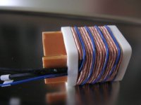
...uhps, I forgot to say, that the pic only shows the primary and the
zero-detection-winding.
Then a triple isolation followed, which can be seen in the pic of my first post. And the secondary for measuring the leakage inductance was a
copper foil, full winding width and 0.3mm thickness.
zero-detection-winding.
Then a triple isolation followed, which can be seen in the pic of my first post. And the secondary for measuring the leakage inductance was a
copper foil, full winding width and 0.3mm thickness.
Eva said:Don't let outrageous safety regulations pi$$ you off. They were written just for that purpose, in order to help big companies to monopolize SMPS development (and EMC actually states for 'Eliminate Minor Competitors').
Have you checked that you have right medication?

I have put couple of small E-trannies apart, and yes they seem to fullfill creepage distance requirements with rather clever structure. Not so much experience from toroids as they are pain in *** to rewind, but that one what i put in pieces was insulated with 15mm wide mylar strip, with 2/3 parts overlap so efectively 3 layers of insulation. Or check almost any chinese piece of sith ATX power supply to pieces, there is at least 6mm creepage distance(wich is enough if primary and secondary sides are grounded?)
Recently i tested all of my junkbox trafos with 5kV ac hipot, all passed without breaktrough. Some of bigger toroids were quite high on leakage, something like 10mA at 5kV, but thats ok. Some double insulated potted E-core was superior to anything else, 0.2mA .
EVA: I think you should be very careful to encourage people to ignore safety regulations. These voltages can be dangerous, so i think Chokoholic's respect for EN60022 (safety for IT equipment) is very well considered.
Chocoholic: Have you thought about a resonance mode push pull converter? IME they are suitable for high power jobs. But forget the 12 V input to the same converter, you will have too much copper on your main transformer. Make 2 separate converters and join them on the secondary side.
Chocoholic: Have you thought about a resonance mode push pull converter? IME they are suitable for high power jobs. But forget the 12 V input to the same converter, you will have too much copper on your main transformer. Make 2 separate converters and join them on the secondary side.
Eva said:Don't let outrageous safety regulations pi$$ you off. They were written just for that purpose, in order to help big companies to monopolize SMPS development (and EMC actually states for 'Eliminate Minor Competitors').
All you Greens should look at it this way -- any noise created by an SMPS is wasted energy.
I am sure that GE, Siemens and Phillips would recommend that their CAT scanners be situated near unshielded ATX power supplies.
Oh, it's always very healthy to have some safety regulations, but something is going terribly wrong when they are routinely ignored for certain classic applications and by big companies without nobody complaining. I have to go now but I will put some examples later.
Same goes for emission and susceptibility regulations, it's healthy to have regulations but something is going terribly wrong when no small company can afford costly though simple approval procedures and they are not allowed to certify equipment by its own, thus then can't develop and sell switching equipment, even though they may actually met regulations.
Anyway, I think that Chocoholic got the point.
I already had a look at the assortment from Buerklin,mzzj said:Forgot to mention that toroids are usually? only class-I approved so you need grounding of primary side also.
Edit: and with little extra money Class-II
they offer potted, magnetic shielded and class II suitable torroids
for around EUR 100,- for 250VA or 300VA.
But this does not look for me like a bargain and also their primary
is a single winding, suitable for 240V only....
Lars Clausen said:EVA: I think you should be very careful to encourage people to ignore safety regulations. These voltages can be dangerous, so i think Chokoholic's respect for EN60022 (safety for IT equipment) is very well considered.
Chocoholic: Have you thought about a resonance mode push pull converter? IME they are suitable for high power jobs. But forget the 12 V input to the same converter, you will have too much copper on your main transformer. Make 2 separate converters and join them on the secondary side.
Is there a reason why you consider EN 60022? During my search I came to the conclusion that EN60065 would be the perfect match, its title is definitely adressing to Audio-, Video- and similar electronic gear.
Don't worry, not even EVA could convince me to ignore the safety standards. She's got the typical southern relaxed position in this regard, and please note: She also implements 5mm creepage her designs.
I am more the accurate German. I don't mind to work with non isolated kVs. But after closing the casing, it must be baby save.
..."...forget the 12V input..."
Uhps, you calculated that I would get current peaks of 300A on my
primary right?
I agree, that 500W PFC-flyback from 120V....274V/AC to 12V/DC is
is crazy. And honestly speaking in the moment this fact would be the only reason for me to try.
With respect to size, weight etc., my clear brain would indicate a
50Hz transformer as the heavy Electrolytic caps for 12V are necessary anyway....
Resonance push pull converter:
Honestly speaking: No, I did not consider this up to now.
I considered a traditional PFC-boost converter followed by an
halfbridge which is switching to an transformer with reasonable leakage inductance to allow regulation of the +/-50V output.
But it's an two stage design. Furtheron it does not use the existing 2F energy storage, so I would need about 200µF/500V at the output of the boost converter......

Hmm, I Am intrested to hear about these, at least here at Finland local authorities are withdraving hundreds of products from markets every year nowadays(mostly chinese CE-****). Quality of electrical products has dropped dramatically in here after harmonised european safety regulations, maybe thanks to southern europeansEva said:Oh, it's always very healthy to have some safety regulations, but something is going terribly wrong when they are routinely ignored for certain classic applications and by big companies without nobody complaining. I have to go now but I will put some examples later.
With Chinese pieces of **** it is enough that some underage slaveworker is sticking CE-stickers to their products and nobody is checking it for real. Then in here TUKES is doing some supprise test for products in market and quite often ordering importer to withdraw their s*it.
Ever seen cheap 6-20 euro multimeter like this?
http://www.tukes.fi/kuvat/myyntikiellot/per_040210-04_y.jpg
Have only 3.5mm creepage distances on PCB, reguired is 20mm for 1000V classII meters. Will explode before reaching 1kV
Eva said:
Anyway, I think that Chocoholic got the point.
I think I got it. "No need to be cleaner than the pope".
But safety ... I am not afraid about my own safety, because
I know what I am handling with.
But friends? Children? Or if I decide to sell the stuff in some years?
mzzj:
Don't you know the Chinese interpretation of CE?
"China Export."
Or about copyright?
"Copy's right."
...somehow I like these guys *lol*
Chocoholic,
I don't know but quite sure it's the same in Germany as in some other Northern european countries, you are NOT allowed to sell or even give away or let it be operated by others a design you have made in private that is not approved with the electrical safety regulations if it's going to be connected to the mains, so you don't have to worry about your friends etc.
Flyback for 500W, you will have huge currents through the secondary diode, maybe upto 200 A peak... the problem with Flyback and high power is switchng losses.
BTW I was a bit puzzled LC mentioned EN 60022(eg. CISPR 22) when talking about electrical safety, its an EMC standard dealing with radiated and conducted emissions.
I think Choco got it right, heres a note of the exact versions to be used:
The last date for evaluation and production to EN60065:1998 is 1st March 2007, when it too will be superseded by EN60065:2002 (which will apply until further notice.
In general:
BTW, talking about creepage and clearance distances, when designing transformers for SMPS one must leave a distance towards the sidewalls of the coilformer, which means one have to put yhe winding layers without support from surrounding walls.
This have made me wondering for many years how we can trust such winding will stay in place.
Distance are needed because it prevent dielectric breakdown between electrodes caused by the ionization of air. The dielectric breakdown level is further influenced by relative humidity, temperature, and degree of pollution in the environment, so one have to also take into account the pollution degree.
Well, but theres a solution, one can always pour the transformer in a plastic pot which will give much smaller creepage and clearance distances, and there wont be any problem with the pollution degree class as in such case its the lowest.
However at least 3 layers between primary and secondary with a good tape and preferably a suitable glue/silicone between primary and secondary at the peripheral "winding package" in the coilformer(not inbetween the winding layers) will do a lot for DIY:ers.
Michael
How did cellphone chargers pass safty standards? The whole transformer in them have a size only less than 20mm. Also...laptop adaptors are small.
Maybe use some special insulation wire / material?
Maybe use some special insulation wire / material?
ChocoHolic said:-The safety standard EN 60065 (Table 11) would require enormous creepage distances for reinforced isolation. Safety class II is a must for me as I do not want to have a mandatory earth connection.
In case of a flyback I would end up in a minimum creepage of
12.6mm and in case of PFC-Boost + Halfbridge around 10mm.
...values which make a suitful small sized transformer difficult...
Re: Re: Torroid vs. SMPS
Vacuum potting helps with creepage distances as you dont need to care about creepage in trafo after it is vacuum impegrnated in epoxyKenshin said:How did cellphone chargers pass safty standards? The whole transformer in them have a size only less than 20mm. Also...laptop adaptors are small.
Maybe use some special insulation wire / material?
Yes, but it is sometimes hard to pass the certification with vaccuum potted designs.
Typically the certification institute cuts the transformer into thin slices and if they find any bubble, you can go home and try another improvement to manufacture it really perfect.... ...experienced this in my old company and our vaccum potting was definitely not a poor potting !!!
Aside potting there are special wires and special bobbins.
Ultima Thule said:Chocoholic,
I don't know but quite sure it's the same in Germany as in some other Northern european countries, you are NOT allowed to sell or even give away or let it be operated by others a design you have made in private that is not approved with the electrical safety regulations if it's going to be connected to the mains, so you don't have to worry about your friends etc.
I am not a lawyer, but I thought you are allowed to give away or sell. But you will be responsible with your life for anything that might happen. If you ignore safety standards and something happens, then you are in trouble.
Ultima Thule said:
In general:
BTW, talking about creepage and clearance distances, when designing transformers for SMPS one must leave a distance towards the sidewalls of the coilformer, which means one have to put yhe winding layers without support from surrounding walls.
This have made me wondering for many years how we can trust such winding will stay in place.
Michael
The unused volume is often filled with 'margin tape'.
It is simply wound at the side wall, or can substitute the side wall if fixed properly. The isolation between the layers must extend throughout this margin tape (See my pics above).
Instead of margin tape there a special creepage spacers, which can be clipped on the bobbin.
If you are able to wind without margin tape or spacers, you ensure
that the windings will stay in place by a simple impregnation with varnish. Varnish also helps to reduce noise and improves humidity properties.
These are some evidences showing that safety standards are usually ignored in the equipment we routinely use in real life.
Most AT and ATX PC power supplies doesn't include any creepages in their transformers, altough their labels are loaded of approval symbols:
This one has CE marking...
But no creepages at all...
This one has a bunch of seals...
But no creepage at all...
This other one had also a lot of seals...
But it not only lacked creepage but its common-mode EMI filter was also missing! Note the jupered common-mode choke and absent capacitors:
mzzj you should check the PSU of your computer(s), you may have been using a unit without creepages for years without even knowing it, like most of us.
But, no doubt, where creepage is always mising is in 50Hz E-I mains transformers. I have still never seen a 50Hz transformer with creepage in my whole life, and these are the ones used in most commercial audio equipment and in most DIY projects.
This one is from my preamplifier, I bought it brand new in an electronics store some time ago:
No creepage at all...
This other one is an isolation transformer from a 12V 50W halogen lamp:
And concerning these toroid transformers that everybody uses for audio assuming they are absolutely safe...
These two pictures are from a 1000VA unit that suffered from an intermittent short between adjacent turns in one of the secondary windings. I stripped the secondary windings to further investigate the effects of overheating on insulation.
Note how the plastic tape (not mylar, maybe PVC?) has melt badly leaving primary-side and secondary-side magnet wires in direct contact far before the wires had any chance to overheat (temperature probably never exceeded 90ºC):
Also note how the insulating tape (and magnet wire enamel) is always badly stretched on the corners of 50Hz toroids, leaving a very thin insulation layer and increasing leakage dramatically:
Why are we not dead? We are still alive because creepage requirements are outrageous. Magnet wire enamel has usually over 3KV dielectric strenght (more like 5 or 7KV) and mylar tape also whitstands more than 3KV per layer. Furthermore, in order to start an arc between two needle shaped electrodes placed 5mm apart, more than 5KV are required, and this is the worst case, since 50KV or so would be required in order to start an arc between insulated round electrodes placed 5mm apart (like magnet wires).
This means that even a transformer without any creepage will pass flawlessly all classic '3,750V for 1 minute' insulation tests, it may even pass a 10KV or even 20KV test depending on construction.
This also means that any multimeter with 3.5mm creepage between +V and -V PCB tracks is probably going to reliably measure 2KV or even 4KV without PCB arcing, altough resistors will suffer breakdown with such high voltages. So in case any government decides to whitdraw them from the market, it would be actually for any reason other than objective reliability, probably economics and company fights.
(check this out as a refference http://www.kronjaeger.com/hv/hv/msr/spk/ )
Chocoholic:
Now try to figure out how much voltage is required to get an arc between two insulated magnet wires placed 10mm apart
And even though, I'm sticking to 5mm creepage, and this already makes my transformers far safer than most ones everybody is using for audio. Then again, does tube gear dealing with 480V use 10mm creepage? No, it doesn't, and their chasis isn't even earthed!
Anyway, as Ultima Thule mentioned, even if you build equipment following all safety regulations, if anybody (other than you) uses that equipemt, it will be a violation of law and you may be lawsuited and jailed. It won't matter if your equipment is objectively safe or not, what matters is that you have to pay dozens of thousands of euros to certification agencies in order for your equipment to be lawful. Nowadays safety is a question of money, not creepages, you must buy it.
kenshin:
I've just opened the off-line battery charger from my old Nokia 3210 phone. It's a self-oscillating flyback. It uses a special magnet wire with a very thick insulation for the secondary winding and standard magnet wire for the rest. Creepage is 5mm (total) and it's certified as a double insulated product. It doesn't have a primary-to-secondary common-mode shunting capacitor.
Safety regulations should be dictated by objective physics, not by economics, politicians and convenience. That's why production and design is progressively shifting towards China: Safety regulations in USA and Europe are dictated and strongly biased by big companies and by the own safety certification companies (these ones that charge you 30.000 euro for each approval), with the only purpose of preventing small companies from growing in order to avoid competence.
On the other hand, Chinese companies are free to grow in their country, until they can afford approval costs in order to enter our market. Ironically, their electronics market is free while ours is under a strong dictatorship.
Most AT and ATX PC power supplies doesn't include any creepages in their transformers, altough their labels are loaded of approval symbols:
This one has CE marking...
An externally hosted image should be here but it was not working when we last tested it.
But no creepages at all...
An externally hosted image should be here but it was not working when we last tested it.
An externally hosted image should be here but it was not working when we last tested it.
This one has a bunch of seals...
An externally hosted image should be here but it was not working when we last tested it.
But no creepage at all...
An externally hosted image should be here but it was not working when we last tested it.
This other one had also a lot of seals...
An externally hosted image should be here but it was not working when we last tested it.
But it not only lacked creepage but its common-mode EMI filter was also missing! Note the jupered common-mode choke and absent capacitors:
An externally hosted image should be here but it was not working when we last tested it.
mzzj you should check the PSU of your computer(s), you may have been using a unit without creepages for years without even knowing it, like most of us.
But, no doubt, where creepage is always mising is in 50Hz E-I mains transformers. I have still never seen a 50Hz transformer with creepage in my whole life, and these are the ones used in most commercial audio equipment and in most DIY projects.
This one is from my preamplifier, I bought it brand new in an electronics store some time ago:
An externally hosted image should be here but it was not working when we last tested it.
No creepage at all...
An externally hosted image should be here but it was not working when we last tested it.
This other one is an isolation transformer from a 12V 50W halogen lamp:
An externally hosted image should be here but it was not working when we last tested it.
An externally hosted image should be here but it was not working when we last tested it.
And concerning these toroid transformers that everybody uses for audio assuming they are absolutely safe...
These two pictures are from a 1000VA unit that suffered from an intermittent short between adjacent turns in one of the secondary windings. I stripped the secondary windings to further investigate the effects of overheating on insulation.
Note how the plastic tape (not mylar, maybe PVC?) has melt badly leaving primary-side and secondary-side magnet wires in direct contact far before the wires had any chance to overheat (temperature probably never exceeded 90ºC):
An externally hosted image should be here but it was not working when we last tested it.
Also note how the insulating tape (and magnet wire enamel) is always badly stretched on the corners of 50Hz toroids, leaving a very thin insulation layer and increasing leakage dramatically:
An externally hosted image should be here but it was not working when we last tested it.
Why are we not dead? We are still alive because creepage requirements are outrageous. Magnet wire enamel has usually over 3KV dielectric strenght (more like 5 or 7KV) and mylar tape also whitstands more than 3KV per layer. Furthermore, in order to start an arc between two needle shaped electrodes placed 5mm apart, more than 5KV are required, and this is the worst case, since 50KV or so would be required in order to start an arc between insulated round electrodes placed 5mm apart (like magnet wires).
This means that even a transformer without any creepage will pass flawlessly all classic '3,750V for 1 minute' insulation tests, it may even pass a 10KV or even 20KV test depending on construction.
This also means that any multimeter with 3.5mm creepage between +V and -V PCB tracks is probably going to reliably measure 2KV or even 4KV without PCB arcing, altough resistors will suffer breakdown with such high voltages. So in case any government decides to whitdraw them from the market, it would be actually for any reason other than objective reliability, probably economics and company fights.
(check this out as a refference http://www.kronjaeger.com/hv/hv/msr/spk/ )
Chocoholic:
Now try to figure out how much voltage is required to get an arc between two insulated magnet wires placed 10mm apart
And even though, I'm sticking to 5mm creepage, and this already makes my transformers far safer than most ones everybody is using for audio. Then again, does tube gear dealing with 480V use 10mm creepage? No, it doesn't, and their chasis isn't even earthed!
Anyway, as Ultima Thule mentioned, even if you build equipment following all safety regulations, if anybody (other than you) uses that equipemt, it will be a violation of law and you may be lawsuited and jailed. It won't matter if your equipment is objectively safe or not, what matters is that you have to pay dozens of thousands of euros to certification agencies in order for your equipment to be lawful. Nowadays safety is a question of money, not creepages, you must buy it.
kenshin:
I've just opened the off-line battery charger from my old Nokia 3210 phone. It's a self-oscillating flyback. It uses a special magnet wire with a very thick insulation for the secondary winding and standard magnet wire for the rest. Creepage is 5mm (total) and it's certified as a double insulated product. It doesn't have a primary-to-secondary common-mode shunting capacitor.
Safety regulations should be dictated by objective physics, not by economics, politicians and convenience. That's why production and design is progressively shifting towards China: Safety regulations in USA and Europe are dictated and strongly biased by big companies and by the own safety certification companies (these ones that charge you 30.000 euro for each approval), with the only purpose of preventing small companies from growing in order to avoid competence.
On the other hand, Chinese companies are free to grow in their country, until they can afford approval costs in order to enter our market. Ironically, their electronics market is free while ours is under a strong dictatorship.
kenshin:
Sorry, creepage in that Nokia charger is actually 4mm, I've taken some pictures:
Note the thick secondary wire...
Also note that the secondary is shifted 4mm from the primary connections and a small flux band is used to reduce the stray field created. Standard wire is used in the primary side.
Overall PCB view showing a 4mm spark-gap.
Sorry, creepage in that Nokia charger is actually 4mm, I've taken some pictures:
Note the thick secondary wire...
An externally hosted image should be here but it was not working when we last tested it.
Also note that the secondary is shifted 4mm from the primary connections and a small flux band is used to reduce the stray field created. Standard wire is used in the primary side.
An externally hosted image should be here but it was not working when we last tested it.
Overall PCB view showing a 4mm spark-gap.
An externally hosted image should be here but it was not working when we last tested it.
- Status
- This old topic is closed. If you want to reopen this topic, contact a moderator using the "Report Post" button.
- Home
- Amplifiers
- Power Supplies
- Torroid vs. SMPS