Hello, I am making a +-40V car amp PS with the 494 and as I can say i experience some problems with making it work normally.
First of all if someone could tell me what noises should be heard from the PS when not loaded? Should the sound be smooth and regular because i can say i hear some "misbehaviors" around the center frequncy. Also i have a very big startup peak of about 10-15A in the 14V. I also doubt about the toroid i am using.It is around 40x25x10 with M 2000. I dont know if it is suitable for the job. I cannot adjust the frequncy somehow cus when i load it it makes awful sounds and the Amper meter jumps where it is not supposed to go for that load. The FETs are IRFP150N.
I would be gratefull If someone could add anything to my problem and if unsufficient i could bring some more info about this project. thank you all!
Member
Joined 2004
We need more information
Hi:You will need to provide a lot more information if you want any help.First of all what is your switching frequency,are you using push pull configuration?,how did you determine the proper number of turns for your core?...
If you can post a schematic of your design it would help towards getting the ball rolling. RC
You don't want to run a switching power supply "unloaded" -- the value of the inductors are inversely related to the load!
Send me an email privately and I will send you the article on how to mod an ATX supply -- it describes the theory well and uses the TL494. The author wrote it for a ham radio magazine -- in their applications the current demand will run from a few hundred MA to tens of amps -- and they need very quiet performance.
Send me an email privately and I will send you the article on how to mod an ATX supply -- it describes the theory well and uses the TL494. The author wrote it for a ham radio magazine -- in their applications the current demand will run from a few hundred MA to tens of amps -- and they need very quiet performance.
Member
Joined 2004
Member
Joined 2004
maybe i have to give up with this and just repeat someone other's design which at least is known to be working.The problem is that i want to use 494 and the schemes i found with it somehow didn't like them. Some of them were without voltage regulation, something i need. I am now searching for sg3525 or 24 for they are more often used. I haven't got any luck of finding it so far! It may sound weird but when some electronic component is not made in your country it's sometimes hard to find it as the only way is import.
Anyway if i have any further experience with the PS i would post here
Anyway if i have any further experience with the PS i would post here
The first step is allways to get the switching and EMI stuff right, then you can mess with the regulation loop.
Do you own an oscilloscope? Trying to do SMPS experimentation without one is like being deaf and blind. Waveforms will always tell you if your circuit is working properly or not.
Do you own an oscilloscope? Trying to do SMPS experimentation without one is like being deaf and blind. Waveforms will always tell you if your circuit is working properly or not.
djQUAN said:in a normal SMPS there should be no sound. is the sound that you hear more like a whistle? if so, the cores or the windings are vibrating which is not a good thing. have you seen the input/output waveforms of the transformer?
A hint of complication....I agree with Eva ....But above comment not always true........some traditional smps circuits will run into burst mode when output is unloaded.....in otherwords the duty cycle can run cyclic undefined in very narrow pulse widths. There's nothing wrong in this other than the slight sizzling noise......however in some toplogies (e.g phase shifted ZVT) is highly dangerous practice. The off-load condition is a severe test for smps stability. In telecom apps this is a standard compliance test.
If the inner current loop in current mode operation has no real current to measure other than nagnetising current the oscillator ramp cannot follow the inductor current.....(because it's near nil) so narrow waveform jitter can result. simple
In Voltage mode, a definite and distinctive squeal spells trouble could be due to core saturating as switching cycles are never quite equal per push pull half or as the outer regulation loop has a badly designed r/c filter pole. This is also true for current mode.
Viewing the inner loop current ramp waveform on a scope is like heart diagnosis for humans........can show up alot of evils.
richj
Yes, i have a 15MHz oscilloscope, which should be sufficient for the purpose. I have seen the primary waveform but some kind didn't like it. I am on my way of puting isolation transistors between the 494 and the fets if this could help something.
Now i have other troubles around the car and this will wait some time")
Now i have other troubles around the car and this will wait some time
500mA is a bit on the high side, 100 to 250mA would be more usual.
Something may be wrong, but I would need to see the circuit and gate/drain switching waveforms in order to know what's going on.
You can detect transformer saturation by looking at drain waveforms during turn-off with a light load (1 to 5 watts). In case of saturation, the drain voltage of one side will spring like hell to 30..60V and will show substantial ringing (this means that there was a big current flowing before turn-off), while the drain voltage of the other side will rise slower and to a lower value, and will show less ringing (this means that there was almost no current flowing).
If both drains spring and ring violently even with light load, it usually means that saturation is happening in both directions, so either frequency or primary turn counts have to be increased.
You should also check the existence of dead time. Use a very light load (1 watt or so) and look at drain turn-off waveform of one side versus gate waveform of the other side (dual oscilloscope required). Ensure that, just after turn-off, the drain voltage of each of the MOSFET sets has had at least 250ns to rise freely before the other side starts turning on. Add more dead time if required. Rise times will decrease for higher loads so this guarantees proper dead time in all circumstances. Enhancing gate drive may reduce rise times and allow for smaller dead times.
This free rising period is critical for proper flux balancing of the transformer. It corrects flux imbalance because a higher magnetizing current causes a faster voltage rise, so slightly less volts*second are applied in that direction and more are applied in the other, thus automatically balancing the flux. Adding snubbers linearises the capacitance seen by each primary leg, so it actually enhances flux balancing, note that MOSFETs show very non-linear output capacitances. It's a quite subltle and unknown mechanism but it works fine.
Hi Eva, I am still a beginner in this kind of stuff that is why I came here to ask those who know it. I am experiencing a problem i cannot understand but still have the hope that sooner or later I will. 
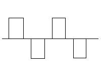
I tried to unplug the fets and see with the oscilloscope what happens on the output of the 494 unloaded.
I saw a perfect picture of what should be seen there. Sorry for the handwork since I don't have a camera here.
I tried to unplug the fets and see with the oscilloscope what happens on the output of the 494 unloaded.
I saw a perfect picture of what should be seen there. Sorry for the handwork since I don't have a camera here.
Attachments
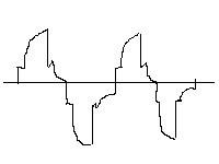
I put a variable resistor on the DTC pin 4 between the reference aregulator and GND to manage the dead time, which was quite clear adjusting when no fets where connected to the IC. When i put them I got something like this on the gates:
I don't know if this is right, may be it is not thus i hoped to see the same wave and not this.
I don't know if this is right, may be it is not thus i hoped to see the same wave and not this.
Attachments
- Status
- This old topic is closed. If you want to reopen this topic, contact a moderator using the "Report Post" button.
- Home
- Amplifiers
- Power Supplies
- SMPS noises with TL494