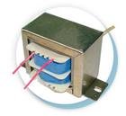
The thing usually used for common mode EMI filtering.
It contains two isolated spaces for wiring (like most of the 50Hz isolated transformer). So I wonder if it's a safer/easier choice for making switching transformer in isolated SMPS run off 220V AC mains.
But the size? It's the biggest one available. For bigger power...need several ones in parallel?
It contains two isolated spaces for wiring (like most of the 50Hz isolated transformer). So I wonder if it's a safer/easier choice for making switching transformer in isolated SMPS run off 220V AC mains.
But the size? It's the biggest one available. For bigger power...need several ones in parallel?
Attachments
Hi Kenshin
Find the datasheet for the CM choke core material and check the specific losses for the core material against a more conventional SMPS ferrite such as 3C90. The CM choke cores do not have to accomodate big flux swings at high frequency, so I suspect you'll find the material they use would have excessive losses at even low SMPS frequencies like 40kHz.
Another issue is that if you use the split bobbin, nice as it seems, the separation of the primary and secondary windings will result in increased leakage inductance, which you don't want. Rather consider a conventional E or ETD core chosen for best efficiency at fs, and use interleaved split primary and secondary windings for minimum L_leakage.
Cheers
John
Leakage inductance is nothing to me -- even something useful to limit short circuit current.
Hi,
I once thougt so also. I made series resonant converter for capacitor charging by winding primary and secondary winding each on opposite posts of UI 93 ferrite core. Transformer was a complete success, 22uH leakage inductance was just what was needed.
Imagine my surprise when we were designing mains filter for the whole machine. While neighbouring frequencies from PFC converter were attenuated by 80 db, I couldn't attenuate third and fifth harmonic of the converter by more than 20db.
At last we have found out that the problem was stray magnetic field of the leaky transformer. Those harmonics were not passing through filter unattenuated, they were actually induced in the filter coils. There was 20cm distance and two 1.5mm thick steel walls between filter and transformer. Finally we had to move the mains filter some 0.5m away from the transformer.
Best regards,
Jaka Racman
Hi,
exactly, leakage flux of the transformer was inducing voltage in filter common mode chokes.
I do not know if you are using classic series resonant converter (halfbridge or fullbridge with series L-C- transformer connection and full wave rectifier without output inductors)? That is what I use for capacitor charging applications. Series resonant converter operating at fixed frequency approximates ideal current source and is short circuit proof without any control.
You might want to control output current by changing repetition frquency of pulses (resonant frequency is determined by LC and is constant). I used dual monostable for control circuit in ring connection (one monostable triggers the other and vice versa). One monostable has fixed pulse lenght and is used to determine on time of the switches, other has pulse lenght determined by current source. I used OTA CA3080 or simple pnp transistor for that, and monostable was 74HC221 or CD4538. This simple circuit acts as VCO with up to five decades variable frquency. There are also integrated controllers like UC3860 and ONsemi part, but I have never used them.
For power stage I even used inverter grade SCRs in my first implementation, but nowadays i use IGBTs with fast antiparallel diode. Since all semiconductors operate in zero current switching regime, switching loses are relatively low. I could operate up to 100kHz resonant frquency with 20kW peak power using 600V IGBts. For lower powers (up to several KW), resonant frquency can be even higher.
In later designs I did not repeat the same mistake (using leaky transformer for resonant inductor). I now use MPP toroid for resonant inductor, but even here I have problems with leaky magnetic flux. I use low permeability core (mu relative = 26) with relatively low number of turns (some gap between adjacent turns) and even in this case harmonics of resonant converer show higher peaks in EMC measurment than harmonics of preceeding PFC boost converter.
Best regards,
Jaka Racman
Jaka Racman said:
For power stage I even used inverter grade SCRs in my first implementation
Is your switching frequency fs below the resonance frequency fo or above it?
SCR can only be used when fs<fo (ZCS).
and electronic ballast circults have fs>fo (ZVS).
These cores will probably be suitable for power transformer applications but splitting the coils increases leakage inductance unnecesarily
Excess leakage inductance is particularly troublesome in flyback converters and its variants, while Push-pull ones are more forgiving about it
Excess leakage inductance is particularly troublesome in flyback converters and its variants, while Push-pull ones are more forgiving about it
- Status
- This old topic is closed. If you want to reopen this topic, contact a moderator using the "Report Post" button.
- Home
- Amplifiers
- Power Supplies
- Is common mode filter core suitable for switching transformer?