Hi everybody!
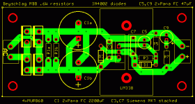
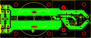
This is a tentative layout for the Carlos Filipe Machado (thanks for sharing, Carlos!) regulated and snubberized PS discussed here :
I have a few doubts about the weird layout I used to parallel two Panasonic FC 2200uF caps in place of the required 4700 uF single cap. Is there anything wrong in that?
I did my best to follow the datasheet and the advice of various fellow diyaudio-ers in the layout of R3, R5 and C5 (one branch close to the Out pin of the chip, the other close to the load), but I could be wrong.
Another issue is the parasytic inductance of the traces. Anyone can say how bad is it in my pcb? Is there a way to improve it? (larger traces and thermal relief pads)?
Every comment is very very welcome. Thanks in the anticipation to anybody willing to comment.
Massimo
P.S. please note that .6W resistors are used in place of the required 1W resistors. This could work for a 15V power supply, but not for a 30V PS. I'll post soon the ExpressPCB file for anyone using different components from mines.
P.P.S. The heatsink is a Aavid Thermalloy (Digikey code HS276-ND or HS229-ND).
Attachments
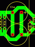
Hi, it would be better to come from the middle of the track between C1A and B rather than comming off the end of one of the caps this way the resistance due to the track is the same for both caps which should make them share a bit better. Since this is regulate it is unlikely that it will make much difference though.
Regards,
Andrew
Regards,
Andrew
Salut, Antomas.
If you want to use two paralleled caps, you would be better to use them in line.
Avoid those corners to the caps.
Make the PSU traces thick and straight, as much as possible.
Looking at the PCB on your first post, mabe you could arrange some space to put the caps in line.
Mabe placing the diodes on each side of the AC plug and tightening the layout on the other places.
But don't make unnecessary corners, and keep traces thick.
If you have to increase the size of the board by 1 or 2 cm it's no problem, right?
Hi Andrew,
thanks for your comments.
I tried this but the result looked like a labyrinth... better using some simpler arrangement like those below.
Ciao e grazie!
Massimo
thanks for your comments.
Hi, it would be better to come from the middle of the track between C1A and B rather than comming off the end of one of the caps this way the resistance due to the track is the same for both caps which should make them share a bit better.
I tried this but the result looked like a labyrinth... better using some simpler arrangement like those below.
Ciao e grazie!
Massimo
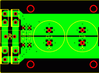
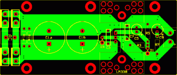
In my second attempt I used thermal relief pads. This feature is not included in expressPCB (at least in my version...), so doing this experiment had really been a pain... somewhere.
What do you think of my experiments? In the meanwhile, heartfelt thanks for all!
Massimo
What do you think of my experiments? In the meanwhile, heartfelt thanks for all!
Massimo
Attachments
antomas said:This is my first attempt:

Yesss!!!
Excelent!
Some more suggestions:
Rearrange D3 so that you can use thick traces.
Mount it vertical if you need.
Attachments
antomas said:What do you think of my experiments?
Great, I like those thick traces.
I wouldn't loose my sleep making those thermal relief pads, though.
You are right it is much better to put the caps in line. I had assumed you had space constraints. The other thing that you need to watch, which is not obvious because you have only implemented one of the regulators, is that you need to connect the two grounds together and use this as return point for the speaker currents. For minumum distortion this should be electrically exactly in the center of the connection between the two regulator grounds, i.e the resistance due to wire or tracks should be the same with the currents involved in power amps this can be quite significant.
I agree if you are going to hand solder the board and it is single sided there is little point in worrying about thermal relief.
Whils it won't hurt to move the diode I really can't see it improving the performance as it is just a catch diode to discharge the caps at power off.
Regards,
Andrew
I agree if you are going to hand solder the board and it is single sided there is little point in worrying about thermal relief.
Whils it won't hurt to move the diode I really can't see it improving the performance as it is just a catch diode to discharge the caps at power off.
Regards,
Andrew
Carlos, Andrew
thanks very very much for your kind and competent advice.
I look forward to drawing a new version including all of your suggestions as soon as I'll recover from a back pain that caught me yesterday.

Grazie di cuore (heartfelt thanks),
Massimo
P.S. are you sure there is not danger of damaging caps when soldering them on such very thick traces (even on a single side pcb)? I never did that...
thanks very very much for your kind and competent advice.
I look forward to drawing a new version including all of your suggestions as soon as I'll recover from a back pain that caught me yesterday.


Grazie di cuore (heartfelt thanks),
Massimo
P.S. are you sure there is not danger of damaging caps when soldering them on such very thick traces (even on a single side pcb)? I never did that...
gfiandy said:Whils it won't hurt to move the diode I really can't see it improving the performance as it is just a catch diode to discharge the caps at power off.
Andrew, the diodes have nothing to do with performance, of course.
That suggestion was too keep the traces thick and straight, and that diode got in the way...
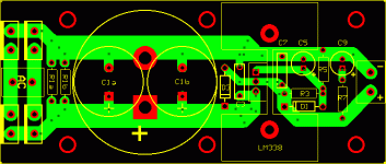
Like it?
New features of this version are:
- larger traces
- "standing up" diodes
- more room for resistors bigger than mines (just drill another hole for each res)
- improved ventilation.
Do you like it?
Thanks once again for your precious help,
Massimo
King of (back) pain
New features of this version are:
- larger traces
- "standing up" diodes
- more room for resistors bigger than mines (just drill another hole for each res)
- improved ventilation.
Do you like it?
Thanks once again for your precious help,
Massimo
King of (back) pain
Attachments
The big heat?
Hi Carlos,
I must have overlooked a not-so-small issue. The heatsinks the pcb is designed for are rated 5 and 4.5 °C/W (say 5 °C/W with the insulating pad).
Are they too little? With a headroom of 10V, the regulator should barely output an average of 1A (10VA -> 50 °C). This is probably enough for a small switching amplifier. From your experience, would it be enough for one (or two?) LM3875 or LM3886 playing rock or symphonic music?
Thanks once again for your help.
Massimo
Hi Andrew,
I'm sorry, i didn't catch exactly your point. Is there any impact of that on the board design or it is just enough to find a suitable (symmetric) point between regulators and amps to be used as a ground star center?
Thanks once again for your help,
Massimo
The other thing that you need to watch, which is not obvious because you have only implemented one of the regulators, is that you need to connect the two grounds together and use this as return point for the speaker currents. For minumum distortion this should be electrically exactly in the center of the connection between the two regulator grounds, i.e the resistance due to wire or tracks should be the same with the currents involved in power amps this can be quite significant.
I'm sorry, i didn't catch exactly your point. Is there any impact of that on the board design or it is just enough to find a suitable (symmetric) point between regulators and amps to be used as a ground star center?
Thanks once again for your help,
Massimo
Re: The big heat?
Well yes, I would use bigger heatsinks and integrate the two rails in one board.
If you are using the PSU with a headroom below 10V (and more than 5v) that should be ok, but only just.
Make two boards and try it.
antomas said:Hi Carlos,
I must have overlooked a not-so-small issue. The heatsinks the pcb is designed for are rated 5 and 4.5 °C/W (say 5 °C/W with the insulating pad).
Are they too little? With a headroom of 10V, the regulator should barely output an average of 1A (10VA -> 50 °C). This is probably enough for a small switching amplifier. From your experience, would it be enough for one (or two?) LM3875 or LM3886 playing rock or symphonic music?
Thanks once again for your help.
Massimo
Well yes, I would use bigger heatsinks and integrate the two rails in one board.
If you are using the PSU with a headroom below 10V (and more than 5v) that should be ok, but only just.
Make two boards and try it.
Power supply design
Antomas,
I assume you want the quietest output you can get? If so you should slit the thick traces at c1b to form an input output to it. The idea being that input and output would be separated except right at the cap. This would lower ripple/noise current contamination of the output. This could be done at both caps for more effect.
In line with all this you should go for the lowest ESR, largest value cap you can fit on the output without the resistor. This way you gain the lowest output impedance over the broadest spectrum. This is very important to lower channel cross talk on 2 channels that are using the same supply.
It would also be nice to put a high quality, multi turn cerment pot between R3 and R5 to tweak the voltage. These regulators are not precision. Aplication charts will show you how to calculate the values for the range you are interested in.
All caps have a self resonate freq. above which they become inductive. Larger ones have a lower freq. Also, 2 caps generally will have a lower ESR than one larger one of the same value. This makes the double cap supply lower impedance and broader bandwidth as well as quieter. Going from 2 to 4 caps would improve the situation again but with decreasing returns, as well as a difficult layout. The only real disadvantages to using multiple large, high quality caps is size, cost and turn on surge. Other wise, go for it if you have the room. I would also recommend only using 105 deg rated caps for their lower ESR, higher ripple current and longer life. Better ones are no bigger than their 85 deg counterparts.
Roger
Re: Power supply design
That RC on the output is the secret of this PSU.
The PSU has very low impedance up to very high frequencies.
Better than any low ESR cap you can use there.
sx881663 said:In line with all this you should go for the lowest ESR, largest value cap you can fit on the output without the resistor. This way you gain the lowest output impedance over the broadest spectrum. This is very important to lower channel cross talk on 2 channels that are using the same supply.
That RC on the output is the secret of this PSU.
The PSU has very low impedance up to very high frequencies.
Better than any low ESR cap you can use there.
- Status
- This old topic is closed. If you want to reopen this topic, contact a moderator using the "Report Post" button.
- Home
- Amplifiers
- Power Supplies
- Weird cap layout in a CFM PS pcb
