Hi Roger,
thanks for the many interesting remarks.
Maybe due to my not-at-all-good english I didn't understand exactly the way to do. Do you know of any pcb picture on the net illustrating this concept?
As far as the big-caps against small-snubberized-caps querelle is concerned (heavily discussed in the chipamp forum, at least for the unregulated PS), Carlos magic recipe found so many experimental confirmations that I definitely want to try it. Maybe one day He'll disclose to us the math behind that...

Thanks once again,
Massimo
thanks for the many interesting remarks.
assume you want the quietest output you can get? If so you should slit the thick traces at c1b to form an input output to it. The idea being that input and output would be separated except right at the cap. This would lower ripple/noise current contamination of the output. This could be done at both caps for more effect.
Maybe due to my not-at-all-good english I didn't understand exactly the way to do. Do you know of any pcb picture on the net illustrating this concept?
As far as the big-caps against small-snubberized-caps querelle is concerned (heavily discussed in the chipamp forum, at least for the unregulated PS), Carlos magic recipe found so many experimental confirmations that I definitely want to try it. Maybe one day He'll disclose to us the math behind that...
Thanks once again,
Massimo
No impact on board design, just as you say make sure you use semetrical point to connect the two grounds together. Preferably as short as possible.
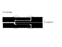
I think what Roger means is a cut through the thick tracks on the center line of the Capacitors. This is so that the capacitor charging current from the bridge have to go to the pin of the capacitor and cannot be drawn past it to the regulator. This seperates the track into the capacitor from the rectifier and an output from the capacitor to the regulator.
Please see very bad paint drawing JPG.
Roger my appolagies if this is not what you meant.
regards,
Andrew
Attachments
Andrew,
This is more what I had in mind, Forgive the poor drawing program. The Idea is to separate the I/O as completely as possible. Doing it this way gives 2 levels of isolation. Actually if the traces were a bit smaller you would get some R/C filtering due to the trace resistance. This can be effective because the peak charging currents will be many times higher than average. In fact, if you have extra voltage to work with, small value resistors (1-10 ohms) can really help reduce ripple noise. These would be placed between the 2 caps on both sides.
Even the best circuits can be contaminated. This is easy to forget when working with quality parts. You still have to do your homework if you want the best performance.
Roger
Attachments
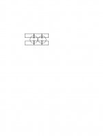
I think there is a trade off here because in your design as you say you get a two level filter, however the charging currents share the central peice of copper with the signal currents drawn from the cap further away from the regulator.
Where as my design does not have the two level filter but the charging and signal currents do not share any copper.
I don't know which one would work better. Roger have you tried a design like this ? Do you know that it works well? If so its probably best to use Rogers solution.
They will both work its just a case of which one is best.
Regards,
Andrew
They will both work its just a case of which one is best.
Andrew,
Exactly right, depends on which parameter is most important in this application. All engineering is determining which compromises to use. In this application low impedance may be more important. I overlooked that this was to supply power amps. Your way would be better, thanks for keeping me honest.
The output cap and resistor question still bother me. I have never seen a chip regulator as solid (low impedance) or as quiet as a good cap. After this unit is built a simple bench test with a load and test signal would settle the issue.
I am glad to see this interest in power supplies. I do more work on power supplies than the actual audio circuits in striving for good sound. Changing things in the circuits may or may not help but a more solid and quieter supply always helps. A simple active load with a power transistor, resistor and input signal can be a real eye opener as to supply quality. The problem with most audio circuits is noise and dynamic compression of the signal. This can be due to nonlinearities or voltage sag due to the wide ratio of peak to average in music. Not that much of a problem for low level circuits as they mostly run in class A but a big problem for power amps.
For power amps to have the best sound the supply must be able to supply these peaks without significant voltage drop. What is significant? I haven’t reached the point where it isn’t significant. No matter how good the amp is at power supply rejection or how good the supply already is, improvements can be easily heard.
Back to trying to get Norton running again! I hate sostware!
Roger
Noise strangler - Roger's version
Andrew and Roger,
thanks very much for your precious advice. I really happy and proud about this thread!
Between one back pain attack and the other , I sketched a new pcb version trying to implement Roger's approach.
Another version following Andrew's approach (better suited for my switching power amp?) will follow soon. How soon depends on the hands of my therapist...
Thanks once again,
Massimo
P.S. Are you aware of any page on the net showing measurements or containing tutorial material pertinent to this topic?
Andrew and Roger,
thanks very much for your precious advice. I really happy and proud about this thread!
Between one back pain attack and the other
, I sketched a new pcb version trying to implement Roger's approach.Another version following Andrew's approach (better suited for my switching power amp?) will follow soon. How soon depends on the hands of my therapist...
Thanks once again,
Massimo
P.S. Are you aware of any page on the net showing measurements or containing tutorial material pertinent to this topic?
Attachments
Antomas,
The thing that I find most is incorrect grounding. If you look through some of the excellent National Semiconductor app notes on analog this will give you some of the knowledge you are looking for. Getting the grounds right is the first step. The way they show error signals creeping in is the same thing that will happen with the voltages being distributed. You have to think of them the same way. Like the star ground points every one talks of, what about star power points? Circuits are getting good enough that the remaining errors can be mostly due to faulty circuit board layout of both grounds and power.
A Google search on these various subjects will give you more than you ever wanted. Here is some of the more useful information;
http://www.analog.com/library/analogDialogue/archives.html
Roger
Roger,
thanks for your answer. In the past I read many papers about grounding, but I didn't found found very much (searched not enough?) about linear regulators. Please note that I just spent two hours searching the Net, Analog Dialogue and the National site, but I couldn't find anything new. If you have some more precise reference, please let me know.
From my known sources, I know that (I'll use the component names of my pcb):
R3 must be very close to regulator
R5 ground point must be very close to load
R5 ground point must be more "noise free" as possible.
Possible changes in PCB are:
1. Connect C7, R5, C5, C9 (maybe C3?) thru separate (tiny) traces to a common ground point near the load (like in Welborne labs PS1);
2. "Strangle the ground trace" on C9 to make it the common ground point, even if the various currents to C9 share the same trace; leave the rest unchanged
3. Like in 2., but connect R7 and C5 to ground AFTER C9 (on the load side).
I suppose (hope) it doesn't matter if a large low-ESR cap (like you suggested) or a small cap with resistor (Carlos way) is used. Maybe with a large cap the star grounding issue is more critical.
Thanks in the anticipation for your answer,
Massimo
PS I tend to remember a discussion on diyaudio about this same issue, but the search function didn't help me either.
Roger,
Rereading my previous message it sounded a bit presumptuous to me (too late to edit). I forgot to say that i'm not an electronic engineer nor an electronic designer, just an implementor, so, in spite of the many papers read (or "scanned") I'm certainly pretty ignorant...
Nevertheless, I enjoy very much drinking from the source of wisdom (diyaudio.com!) and I'd be proud to give back some useful work to the comunity.
Any practical recipe or good reading recommendation is very welcome.
Cheers,
Massimo
Rereading my previous message it sounded a bit presumptuous to me (too late to edit).
I forgot to say that i'm not an electronic engineer nor an electronic designer, just an implementor, so, in spite of the many papers read (or "scanned") I'm certainly pretty ignorant... Nevertheless, I enjoy very much drinking from the source of wisdom (diyaudio.com!) and I'd be proud to give back some useful work to the comunity.
Any practical recipe or good reading recommendation is very welcome.
Cheers,
Massimo
antomas,
It has been a while since I have used any IC type regulators so am not able to give you any up to date information on the one you are using. All my linear type regulators use discrete components to good effect. Generally what you said sounds right. The idea is to keep the ground as close as you can to a pure reference with no outside signals contaminating it. This way when the reference and feedback are compared to it the generated correction will be more accurate and noise free.
Roger
This is similar to what I build
www.edn.com/contents/images/178097f1.pdf
And the explanation for how it works.
www.edn.com/article/CA178097.html
I use a 431 adjustable referance so I can tweak the voltage.
 Stay tuned.
 - Status
- This old topic is closed. If you want to reopen this topic, contact a moderator using the "Report Post" button.
- Home
- Amplifiers
- Power Supplies
- Weird cap layout in a CFM PS pcb