Hello all.
When I build a PSU like a shunt or serie regulator, I am very interested in the output impedance.
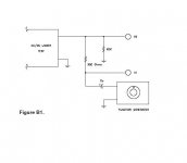
Please look at my attachment and tell me how to calculate the output impedance???.
An exsample with my shunt reg, which is fed from a regulated psu (B&O):
Wavegenerator output = 10Vpp from DC to exsample 100Khz.
and generator output impedance = 50ohm
Output voltage shuntreg DC = 20V
Measured with point RDC 100Khz@2.5mVpp ac. (scope say 2mv with shortened input because off noise in ground wire from regulated psu, else 1mv input shortened)
Can I avoid this groundnoise somehow?
Best regards
Kim
When I build a PSU like a shunt or serie regulator, I am very interested in the output impedance.
Please look at my attachment and tell me how to calculate the output impedance???.
An exsample with my shunt reg, which is fed from a regulated psu (B&O):
Wavegenerator output = 10Vpp from DC to exsample 100Khz.
and generator output impedance = 50ohm
Output voltage shuntreg DC = 20V
Measured with point RDC 100Khz@2.5mVpp ac. (scope say 2mv with shortened input because off noise in ground wire from regulated psu, else 1mv input shortened)
Can I avoid this groundnoise somehow?
Best regards
Kim
Attachments
current flows in loops, the current in your ground return is equal and opposite the current injected into the V2 line by the function generator
you will have much more success in electronic design if you trace out the complete current loop for any signal and understand the impedance in voltage drops induced in all parts of the loop, especially the "ground"
if you pick one physical point in the circuit you can call it ground, for measurement the function generator and oscilloscope should both be connected to this same ground point
Hello Jcx
Yes first it helped a little by taking a separete ground wire to my scope from the psu to reach 2mVpp input shortened.
Maybe if i build a unregulated psu with a transformer, rectifier and capacitor, to lower ground loops from regulated psu??
Anyone about the outputimpedance in psu point RDC / V2?
Best regards
Kim
Zout of switching PSU
Hi kimschips
The output impedance of a switching supply at high frequency is usually dominated by the ESR of the output capacitor/s. These values are available from manufacturers data sheets.
However you go about physically measuring Zout, your result should correlate closely with the overall ESR value.
You can get a ballpark estimation of the ESR in practice by measuring the change in output ripple voltage with a change in load. (Set your scope on 20MHz BW limit so your measurements don't get too messed up by probe groundlead ringing).
Then Zout = DeltaV(ripple) / Delta I(load)
Regards
John
kimschips said:Thank you very much
But what do you measure when you put the probe in psu output,
Wavegenerator 10Vpp put in point RDC, frenquency variable from DC to eksample 1Mhz.
and measure 2.5mV (2mV ground noise) as risses up to to 5mV with 1Mhz?
Best regards
In your schematic you have a signal current going through the 300 ohms into the supply. That current is generator voltage / resistance (ignoring the small ripple on the supply), so for 10Vrms out of the generator your current is 10/300 = 33mA. Your resulting ripple is 2.5mV. Ohms law thus says that the supply output impedance = 2.5mV/33mA = 75mOhms, which is not so hot.
The problem here is that with these low impedances, you have to be very carefull where to measure. For instance connect the 300 ohms at the supply point where the feedback resistor is connected, and measure with a separate wire at the same point. You can easily get an order of magnitude variation depending how/where you measure. In your circuit, the wire coming from the "DC/DC under test" to the 300 ohms could easily represent most of that 75 mOhms.
That also means that you get only the benefit in the actual circuit if you connect the load at the same point, of course.
Jan Didden
Hello
Thank you Jan Didden you hit me there")
The PSU is not with feedback it´s a experiment with a shuntreg in principle as used in LCaudio Zapfilter 1
I put up some schematic later.
Do you think i can minimise ground noise/ ripple if i remove my regulated psu (as feeding my shuntreg) and try with a Unregulated psu, with only a toridol,rectifier and a capacitor.
Kim
Thank you Jan Didden you hit me there
The PSU is not with feedback it´s a experiment with a shuntreg in principle as used in LCaudio Zapfilter 1
I put up some schematic later.
Do you think i can minimise ground noise/ ripple if i remove my regulated psu (as feeding my shuntreg) and try with a Unregulated psu, with only a toridol,rectifier and a capacitor.
Kim
If you post a schematic we can see where to measure/connect the load for best results.
Ground noise/ripple I think is more a function of layout and construction that getting rid of the regulator. The regulator as such will surely have less ripple/noise than the bare rectifier etc, but you need to take care of the implementation to keep it.
Jan Didden
Ground noise/ripple I think is more a function of layout and construction that getting rid of the regulator. The regulator as such will surely have less ripple/noise than the bare rectifier etc, but you need to take care of the implementation to keep it.
Jan Didden
Schematic
Hello
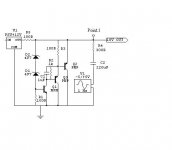
Here is my schematic for the setup i am talking about.
Notice point 1 is output and where I measure with oscilloscope.
R5 is always adjusted so you got about 50 to 100mA running thought your shunt transistor Q2 plus current to your load.
Other transistors are BC556 and 2SC2240GR
The input psu is a variable B&O powersupply.
Best regards
Kim
Hello
Here is my schematic for the setup i am talking about.
Notice point 1 is output and where I measure with oscilloscope.
R5 is always adjusted so you got about 50 to 100mA running thought your shunt transistor Q2 plus current to your load.
Other transistors are BC556 and 2SC2240GR
The input psu is a variable B&O powersupply.
Best regards
Kim
Attachments
- Status
- This old topic is closed. If you want to reopen this topic, contact a moderator using the "Report Post" button.
- Home
- Amplifiers
- Power Supplies
- PSU Output impedance???