Hi..
My freind and I built a smps to produce 240VDC 100mA and 6.3VDC 4A..
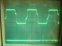
It's running at 40Khz using TL494 and IRF540N Mosfet.
I load the HT with a home 240V bulb rated 18W and the 6.3V o/p loaded with 4 real tubes (6N1P).
I have been powering up the circuit for about a week.. but the transformer core heat up after running it for 30mins..and its reaching up to 50degC... the waveform at the MOSFET drain is always monitored and it never changed at all...
Is the transformer core temp normal??
Attached is the waveform pic...
My freind and I built a smps to produce 240VDC 100mA and 6.3VDC 4A..
It's running at 40Khz using TL494 and IRF540N Mosfet.
I load the HT with a home 240V bulb rated 18W and the 6.3V o/p loaded with 4 real tubes (6N1P).
I have been powering up the circuit for about a week.. but the transformer core heat up after running it for 30mins..and its reaching up to 50degC... the waveform at the MOSFET drain is always monitored and it never changed at all...
Is the transformer core temp normal??
Attached is the waveform pic...
Attachments
Thanks Jack... I m glad that you replied my query here....
Another thing that I forgot to mention is that all the sec winding is winded prior to winding the primary.... and the since the 6.3 is meant to supply around 4 amps, I wind it in bifilar method... and primary is (diy) litz wire.
The question is, can I use bifilar winding? Using litz in the sec makes the winding layer uneven.. thats why I tried the bifilar.
Hi,
nothing wrong with bifilar, even better than single wire. Winding primary over secondary increases primary leakage inductance a bit, but then again no problem if your PS works fine. As long as your transformer is running cool, is properly isolated (required creepage distance along insulation tape layers) and your semiconductors don't fail you are okay. Only remaining problem might be electromagnetic interference issue, but if that's for your home use I wouldn't bother to much. If your TV and radio works fine you have no problem.
Best regards,
Jaka Racman
Hi Jaka,
I am a bit confused here... I've read somewhere that winding all secondary before primary reduce leakage inductance... But its different with your statement...
which is better? winding primary over secondary, or winding secondary over primary?
my concern is to make the transformer runs as cool as it can... i am using this power supply in my car....
currently my transformer temp is constant at 50-55 deg C when I leaveit running for 4-6 hrs everyday fo about 1-2 weeks..
regards..
Hi,
maybe reading those links will make things more clear:
TI Magnetics Design Handbook
Transformer & Inductor Design for Optimum Circuit Performance
Best regards,
Jaka Racman
maybe reading those links will make things more clear:
TI Magnetics Design Handbook
Transformer & Inductor Design for Optimum Circuit Performance
Best regards,
Jaka Racman
SMPS transformer temp rise
Xaudiophile:
50degC is nothing to worry about. One normally would start a transformer design with a spec for maximum temperature rise. This is often set to 30 deg C, seldom more than 40 deg C, and is based on values established by the safety agencies UL, CE etc as follows:
If your transformer were to be subject to qualification to EN60950 or UL60950, the safety geezers would do a temperature measurement of the transformer at full load, by either a thermocouple or by measuring the winding resistance.
Then they calculate:
T(limit) = T(max) + T(measure) - T(max ambient)
Where T(measure) is the ambient temperature at which they took the trafo temp measurement, typically 20-22 deg C
T(max ambient) is the maximum ambient temperature at which you claim your product may be operated, typically 40 degC.
T(max) is an assigned maximum safety temperature of 100deg C (where temp is measured by winding resistance, 90 degC where it's measured by thermocouple)
T(limit) is the max temperature that they may measure during the test if the transformer is to pass EN60950.
Typically this gives us:
T(limit) = 100 + 22 - 40 = 82 deg C
ie a max permissable temp rise of 42 deg C above ambient.
But remember that:
1. The temp they measure is the temp of the winding - perversity dictates they will always measure the innermost winding which has the worst heat exchange with the ambient.
2. Your transformer design calcs - especially thermal estimations of convection based on transformer surface area - are ballpark only.
3. Your limit drops 10 deg C if they measure wioth TC's. Normally you can insist on winding resistance measurements, but there may be cases where this is not possible.
So nearly all transformer designers play safe and set a max temperature rise of 30 deg C above ambient.
I hope this missive was of interest.
Regards
John
John,
Thanks for the explaination.. I am now more relief when Jaka and you replied... I at least not worrying about something where others are not worried... ..
..
BTW, I currently having a problem with my rectifir diode getting hot... Its a UF600, connected in bridge for the 6.3V winding, the total load is only 2.2A. What worry me is the diode getting hot...
My friend suggested that I use the 80SQ45 which has lower Vf...
Can schotky with lower Vf reduce the heat??
Can I parallel 2 schottky? What is the effect?
Thanks again..
Thanks for the explaination.. I am now more relief when Jaka and you replied... I at least not worrying about something where others are not worried...
..BTW, I currently having a problem with my rectifir diode getting hot... Its a UF600, connected in bridge for the 6.3V winding, the total load is only 2.2A. What worry me is the diode getting hot...
My friend suggested that I use the 80SQ45 which has lower Vf...
Can schotky with lower Vf reduce the heat??
Can I parallel 2 schottky? What is the effect?
Thanks again..
Diodes
Xaudiophile: By my reasoning your diodes are each dissippating somewhere between 1.6/2 = 0.8W and 2.4/2 = 1.2W. The factor of two is because they are in bridge. I don't know what package the UF600 diode is, but if it's small axial package like a UF4007 then 1W could make it quite hot. Also, have you checked reverse recovery times of this diode i.r.o. your switching frequency and max duty cycle?
If the heat is genertated from conduction losses, then the lower Vf of a Schottky will help, and the Schottky doesn't have reverse recovery losses so it's really a natural contender for low voltage systems like yours. So use a Schottky.
As to parallelling Schottkies; well yes and no. Strictly speaking you can't guarantee the diodes will share the current equally and the purists would say no. On the other hand if you use a dual rectifier Schottky for each diode in your bridge, then the Schottky diodes in each pair are fabricated together on the same die, and the current sharing probably won't be all that bad in practice. I've seen it done often. If you do this, make sure that each diode in the pair can carry the full current load on its own.
Good luck
John
- Status
- This old topic is closed. If you want to reopen this topic, contact a moderator using the "Report Post" button.
- Home
- Amplifiers
- Power Supplies
- Help!!ETD core warm