
Clearly the UWB is better than the STMicro 7805, curious isn't it that the UWB uses a green LED, discrete error amp, but I don't see a pass transistor capable of much current, perhaps it's on the back.
the measurements done by WJ in 1995 showed that the line rejection of the SuperReg was 40dB better than a 7805, and noise appears to be 10x better -- these were done on an AP-1. I would think that the gaps would be more clearly illustrated -- the test setups obviously vary so there is no consistency -- the measurements should run out to 200kHz -- not easy to do with a sound card FFT --
the measurements done by WJ in 1995 showed that the line rejection of the SuperReg was 40dB better than a 7805, and noise appears to be 10x better -- these were done on an AP-1. I would think that the gaps would be more clearly illustrated -- the test setups obviously vary so there is no consistency -- the measurements should run out to 200kHz -- not easy to do with a sound card FFT --

jackinnj said:The adjust pin of Z203 -- which is a pre-regulator and also works the protection circuitry -- you could put a 100uF electrolytic here -- minding the polarity.
Thanks for your help.
The ADJ pin of Z203 already has a 100uF electrolytic on it and since it is an LM337 - I will need to rearrange the wiring slightly since the Audiocom reg is designed to replace LM7915.
Any further help would be great..........
Sonusthree said:In their defense, they have been selling on Ebay for at least the last 9 months or so for £16.99 ......
That what I paid for mine.....and a long time ago. Like Matin, I have since learned a lot and discovered a few of the DIY boards that are now available. However, these little Audiocom units will fit nicely into the available space.
peranders said:
Per-Anders,
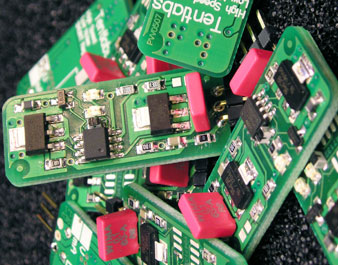
These look almost exactly the same as the Tent Labs supplies!
Jan Didden
Tent Labs are shunt regulators (not sure what types Lars' are) .... and quite different
http://www.tentlabs.com/Components/Shuntcomp/index.html
http://www.tentlabs.com/Components/Shuntcomp/index.html
peranders said:
David Sulzer wrote in the 80's about a type of regulator (nothing new though)
Walter Jung did also write about some other kind of regulator (nothing new either).
Both Mr. Sulzer and Mr. Jung made those regulators known. As we speak we should not forget Mr. Didden who made pcb's for Mr. Jung's article.
A super regulator from 1977, Mr. Kaneda, Japan. Picture here
Anybody who have seen a super regulator before 1977?
Hey, Gents:
You are arguing a design that was 30 yrs. ago design. Today is 2007. Don't you guys get some new design and discuss???
Can you come up with something better? The Super regulator may possibly be improved but how? To make a wideband regulator is quite hard if you look at how the pcb should look like. Note also that the super regulator is very rare in the industry, a LM317 or 78xx is often enough.
This is a shunt from the diyhifi forums. I made surface mount versions and works very well, maybe about $10 in parts from Digikey if you build a few. Put some resistors or even diode to drop more of the CCS voltage (the LM is 1.25 V I think) if you're doing higher current, so you don't exceed the dissipation rating of the current-setting pot.
An externally hosted image should be here but it was not working when we last tested it.
It's adjustable. You need to figure out the current and voltage requirements of your load, and then size parts accordingly.
The CCS current should be set to always exceed the maximum load current. For the voltage, capacitor ratings and the power resistors on top of the shunting device may need to be resized. It's generally for low power stuff, so not output stages")
The CCS current should be set to always exceed the maximum load current. For the voltage, capacitor ratings and the power resistors on top of the shunting device may need to be resized. It's generally for low power stuff, so not output stages
Where is the 200 kHz number from? The impedance of the shunt regulator is flat to well beyond the audio band, and this is a regulator for analog, not digital audio. 35-45 Mhz is too high for analog audio, and too low for a DAC (modern sigma delta / advanced segment DACs have lots of HF power in images extending well beyond that range). The analog amplifier should never see anything exceeding 50 kHz, or else you are using an insufficient analog filter on the DAC outputs.
Here's what the RF professional says about regulation for digital:
http://www.diyhifi.org/forums/viewtopic.php?p=27253&sid=1ae2f47900ba84a45d11422813275b57#27253
The failing in a series regulator is that it doesn't isolate the AC current loops of the load and of the power supply.
Here's what the RF professional says about regulation for digital:
http://www.diyhifi.org/forums/viewtopic.php?p=27253&sid=1ae2f47900ba84a45d11422813275b57#27253
At those frequencies, any regulator is out of the equation. It is all the bypass caps.
The failing in a series regulator is that it doesn't isolate the AC current loops of the load and of the power supply.
peranders said:
Anybody who have seen a super regulator before 1977?
Audio Amateur, 1971 #1 describes a group of high performance (for the day) regulators using discrete devices for the error amp, and Audio Amateur 1974#4 had the first Walt Jung regulator article -- Walt also described IC regulators in the IC Opamp Cookbook. The WJ article used the LM301 -- in this article WJ coined the term "Super Regulator"
Crowbar said:The analog amplifier should never see anything exceeding 50 kHz, or else you are using an insufficient analog filter on the DAC outputs.
You miss the point -- the purpose of getting the supply impedance low through the megaHz are all the unintended consequences of RFI and EMI coupled to the supply lines -- when radio frequency interference, electro magnetic interference, diod noise is rectified by a PN junction even the small offsets cause distortion.
I was only looking at the unity gain bandwidth where you have zero feedback.Crowbar said:Where is the 200 kHz number from?
Take 20 kHz, how much feedback do you have with OPA177 vs AD825?
OPA177 = 30 dB = 30
AD825 = 60-65 dB = 1000
That is the possible differens in output impedance at 20 kHz.
There are at least two parameters that are important:
1 Power supply rejection
2 Output impedance (load regulation)
I guess it's not been an issue in any of my amps (I always test with a 40 MHz scope), as I use proper snubber design in the power supply, and my amps are in metal enclosures.jackinnj said:[diod noise is rectified by a PN junction even the small offsets cause distortion.
In simulation, the design is stable with faster opamps, so I see no problem with the topology itself; you're pointing out a limitation of the specific opamp.
Super Reg.
Hey,
Can you guys imagine a ps that has 100mhz bandwidth, Nowadays, they can design up to this HF ps, from China. As you can see, rocket carrying satellite with 100% successful rating. Don't stayed in the 18th Century with those outdated design. ( 1971 )
Super Reg. is a relied on ADxxx, that is a product from Analog Device, it's costive with compare to other manufacturer, design? use up to date discrete component, such as high speed FETs. This is a tips!
ICs and Op-amp has high amplification factor, but doesn't have fast transpose time, this is the weakest point to utilize them in ps design, other than this, stray capacitance is another factor. lets say, the response time of a bi-polar transistor is much slower than a Fet which just has a resistance region controlled by the gate, and the former one with electron flows thru two junction which controlled by the base.
jackinnj said:
Audio Amateur, 1971 #1 describes a group of high performance (for the day) regulators using discrete devices for the error amp, and Audio Amateur 1974#4 had the first Walt Jung regulator article -- Walt also described IC regulators in the IC Opamp Cookbook. The WJ article used the LM301 -- in this article WJ coined the term "Super Regulator"
Hey,
Can you guys imagine a ps that has 100mhz bandwidth, Nowadays, they can design up to this HF ps, from China. As you can see, rocket carrying satellite with 100% successful rating. Don't stayed in the 18th Century with those outdated design. ( 1971 )
Super Reg. is a relied on ADxxx, that is a product from Analog Device, it's costive with compare to other manufacturer, design? use up to date discrete component, such as high speed FETs. This is a tips!
ICs and Op-amp has high amplification factor, but doesn't have fast transpose time, this is the weakest point to utilize them in ps design, other than this, stray capacitance is another factor. lets say, the response time of a bi-polar transistor is much slower than a Fet which just has a resistance region controlled by the gate, and the former one with electron flows thru two junction which controlled by the base.
- Status
- This old topic is closed. If you want to reopen this topic, contact a moderator using the "Report Post" button.
- Home
- Amplifiers
- Power Supplies
- Invisus ultra super regulator