Hey all.
I wondering how much does a decoupling capacitor do to the sound in a given circuit, like a preamplifier which can operate with an RL from 10K and down to 75R?
I mean modulation and how high in freqency a given capacitor can work up to?
Does a capacitor "destroy" the lower impedance from a regulator in the PSU? (regulator 0.01R- DC to 400Khz)
I think off the limitations for the best 100nF and 100uF capacitor on the market?
In a preamplifier which the powersupply consist of a Shuntreg?
Working from DC to 400Khz -> R= 0.01R.
In a preamplifier which powersupply consist a Jung regulator?
What are the specificattion for a Jung regulator?
Best regards
Kim
Attachments
kimschips said:Hey all.
I wondering how much does a decoupling capacitor do to the sound in a given circuit, like a preamplifier which can operate with an RL from 10K and down to 75R?
Well, considering the probable reasoning behind other things presented in this thread, I can say with certainty that you believe in psychoacoustics... in which case, you can do absolutely anything you want, up to and including parking your car on the other side of the street, to "improve" sound.
I mean modulation and how high in freqency a given capacitor can work up to?
Depends on ESL, and for current capacity, ESR. Given you specify a 10mohm impedance below, I would guess your load, whatever it is, demands a very large current draw. Capacitors will work orders of magnitude more efficiently than your shunt regulator, at supplying the 500 amperes demanded of it.
Does a capacitor "destroy" the lower impedance from a regulator in the PSU? (regulator 0.01R- DC to 400Khz)
Huh? As a parallel circuit element, it can ONLY reduce impedance.
I think off the limitations for the best 100nF and 100uF capacitor on the market?
Anything made for difficult service, polypropylene inverter-grade and snubber caps come to mind; for electrolytics, anything made for switching supplies.
Working from DC to 400Khz -> R= 0.01R.
I wonder what could possibly demand such low impedances; is your circuit indeed drawing the many hundreds of amperes your impedance suggests??
Tim
Hi Kim,
Capacitors emit spurious voltages arising from a phenomenon, among others, called dielectric absorption, something of which Tim has perhaps never heard, though something to which military, aerospace, medical and other industries refer as an important indicator of capacitor behaviour where capacitor behaviour counts most (think cruise missiles, etc). That voltage emission, so-called, will affect the operation of your regulator and degrade the sound of your amplifier relative to an amplifier using a capacitor evidencing less such emission. The only ways I know to diminish deleterious effects of PSU capacitors is to filter and/or cancel the noise they create, and use better quality capacitors. One problem with solid state is you are basically stuck using electrolytic capacitors, which are the worst of breed for capacitors.
Tom
Hello and thanks for reply so fast.
When I wrote R= 0.01R I mean the output impedance off the shunt reg, working from DC to 400Khz.
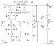
The shunt reg is drawing +-100mA and +-65mA is running in the outstage in shown schematic.
LCAUDIO is claiming 0.01R from DC to 10MHZ with their Shunt reg to Zapfilter 1 and 2.
They said that they constructed such a extreme PSU (+-10V) to avoid capacitors decoupling in the PSU and their "capacitorsound".
How high in freqency is the best 100uF capacitor working to (name)?
www.lcaudio.com -> Cdupgrade -> Zapfilter2
Best regards
When I wrote R= 0.01R I mean the output impedance off the shunt reg, working from DC to 400Khz.
The shunt reg is drawing +-100mA and +-65mA is running in the outstage in shown schematic.
LCAUDIO is claiming 0.01R from DC to 10MHZ with their Shunt reg to Zapfilter 1 and 2.
They said that they constructed such a extreme PSU (+-10V) to avoid capacitors decoupling in the PSU and their "capacitorsound".
How high in freqency is the best 100uF capacitor working to (name)?
www.lcaudio.com -> Cdupgrade -> Zapfilter2
Best regards
When it's about dielectric absorption effects than put there film or mica caps which have the lowest absorption factor. And this is practically difficult because you need cap impedance <<1/(2pix75ohmx20hz)=106uF - quite big size film caps. If there's shunt regulator (zener parallel principle) and imressive 10 mOhm output impedance is real, than maybe about 5uF just for stability issue is enough there?
I have to add that "big" aluminium capacitor like 3300uF/25V has ESR in order of 80-100 mOhm, and spesial "low ESR" type of same value has 20-30 mOhm, and very special "audio hi-fi" type (even bigger trunk) has about 10 mOhm.
You can also consider using another special Sanyo OS-CON type.
I have to add that "big" aluminium capacitor like 3300uF/25V has ESR in order of 80-100 mOhm, and spesial "low ESR" type of same value has 20-30 mOhm, and very special "audio hi-fi" type (even bigger trunk) has about 10 mOhm.
You can also consider using another special Sanyo OS-CON type.
LC Audio’s supply impedance claims appear to be “puffery” – perhaps technically true but actually meaningless – I don’t really care about “esr” in isolation, the total impedance between the load and the supply is what matters and “9mOhm to beyond 10 MHz” is meaningless due to parasitic L being everywhere
– 9 mOhm ~ |150 pH |_10 MHz
but a typical via in a .060” pcb ~ 1 nH (for just 1 via)
soic leads are ~ 1 nH/mm
even trace resistance enters in at these levels: 0.050” wide 1 oz Cu ~ 9 mOhm/in
in a high resolution analog systems low supply impedance is one tool but decoupling of local low level, power and digital supplies+gnds from one another is usually the better place to start – 40 dB of isolation between noisy and quiet supplies is better than using extreme measures to get 100x reduced supply impedance in a common supply architecture – the noise currents can still flow past the quiet inputs and couple to them in a low impedance common supply scheme
http://www.cirrus.com/en/pubs/appNote/an04.pdf
adc v ref discusses peaking in cap bypassed series regulator
http://www.calex.com/pdf/3power_impedance.pdf
series reg output Z peaking with load C
-note that even shunt regulators with output Z < 100 mOhm are using feedback and can show peaking with load C
http://www.pa.msu.edu/hep/d0/ftp/ru...nformation/xilinx_xapp623_decoupling_caps.pdf
for 100MHz FPGA board decoupling, lots of caps – shows (small) antiresonant peaks, these peaks can become large when paralleling leaded caps as commonly recommended by audiophiles without impedance analyzers
(ps the posts discussing dielectric absorption characteristics of caps in the context of mOhm supply impedance decoupling are simply clueless)
Hey
This is very interesting (JCX) with links and explanition with real eksamples and measurement.
ALME look at this link page 15:
http://www.pa.msu.edu/hep/d0/ftp/ru...upling_caps.pdf
I think you hit something there.
If i decouple with the shown capacitors values in the link, will They improve (and lower the supply impedance)? or maybe the capacitors wil rise the supply impedance or just make the decoupling freqency higher as I wanted?
Best regards
")
This is very interesting (JCX) with links and explanition with real eksamples and measurement.
ALME look at this link page 15:
http://www.pa.msu.edu/hep/d0/ftp/ru...upling_caps.pdf
I think you hit something there.
If i decouple with the shown capacitors values in the link, will They improve (and lower the supply impedance)? or maybe the capacitors wil rise the supply impedance or just make the decoupling freqency higher as I wanted?
Best regards
Um, okay.
Please explain to me why dielectric absorption would degrade sound, especially with a 10mohm impedance regulator, especially through the power supply (assuming your circuit was designed well with PSRR in mind, also not suggested by the regulator requirement, which also assumes that you chose a regulator based on the circuit requirements, which I doubt).
Tim
Agree with Tim.
I happened to hear about dielectrical absorption influence only on performance of some input stages of measuring/medical equipment. They like to use Teflon decoupling caps in there.
Kim, sorry but I couldn't open your link.
I think the best power filter solution will be three caps in parallel on each rail: first of aluminium type as low frequency tank, say 1000uF, second of film type, say 2uF, anf third of ceramic SMD type with minimum inductance for radio frequency filtering, say 0,1uF.
Do you like such solution? It is to satisfy different needs
Alme said:I happened to hear about dielectrical absorption influence only on performance of some input stages of measuring/medical equipment. They like to use Teflon decoupling caps in there.
So why use teflon caps in that application?
Hey
Alme look at JCX link nr 3 page 15 -> I could use 10uF for the outputstage and 220nF decoupling with inputstage PSU lines??
Look also at JCX link nr 1 with 10uF and 100nF decoupling
I think it dosn´t matter with 1000uF cap when my shunt reg have 0.01R output impedance down to DC??
What is teflon caps and what can they do that others can´t?
Best regards
kimschips said:What is teflon caps and what can they do that others can´t?
Not much. Polypropylene is about the best out there, and cheap to boot.
Tim
- Status
- This old topic is closed. If you want to reopen this topic, contact a moderator using the "Report Post" button.
- Home
- Amplifiers
- Power Supplies
- Capacitor limitations??