Hi Terry,
With your devices you should be safe up to 50V rails. The variac test is irrelevant, though, IMHO, as you need to check if the pass transistor survives the initial situation (full input voltage and 0 output voltage). If you slowly increase the input voltage, the output increases as well and that's not relevant for what you want to check (but it's still a valid test for the amplifier MOSFETS)
Cheers!
The variac test is irrelevant, though, IMHO, as you need to check if the pass transistor survives the initial situation (full input voltage and 0 output voltage). If you slowly increase the input voltage, the output increases as well and that's not relevant for what you want to check
Yes, but Terry can pre-set the variac to yield the appropriate output and switch the mains on / off to test using an conventional switch. I think he just wants to use an on hand transformer to check the 50V operation and that should be fine.
Initial cold-start would be the most stressful condition during normal use. The main reservoir / filter capacitors come up to full voltage quite quickly while the output is still at or near zero voltage. This places the full available supply voltage for each rail across its respective pass MOSFET and could allow for considerable short term dissipation in those devices should any appreciable current be drawn.
Under normal use this won't be an issue. I can only see it becoming an issue in the event of a failed amplifier being fed by the CM supply where the output voltage is pinned down by a near short circuit and a large current is allowed to flow. This is where a high sustained dissipation is possible while the fuse is still intact and the reservoir capacitors still have plenty of energy stored. That said, personally I'd test new or freshly worked on amplifiers on a basic CRC supply and when there is a clean bill of health put them on the CM supply.
Under normal use this won't be an issue. I can only see it becoming an issue in the event of a failed amplifier being fed by the CM supply where the output voltage is pinned down by a near short circuit and a large current is allowed to flow. This is where a high sustained dissipation is possible while the fuse is still intact and the reservoir capacitors still have plenty of energy stored. That said, personally I'd test new or freshly worked on amplifiers on a basic CRC supply and when there is a clean bill of health put them on the CM supply.
Apologies, reading again it is (now) clear what you've saidYes, that is the plan, to set the variac to the proper voltage and then I can just switch it on. So you guys are saying that the initial turn on is the biggest strain on the circuit? The voltage come up slowly on the output. I will try it today sometime.
Blessings, Terry

Agree with Jason, the huge dissipation during startup can only occur in extreme conditions.
But the problem is different...
The VOLTAGE stress might still occur though even without a load: the aim for 50V output leads to approx 51V nominal at the input, and if we accept a +/-10% tolerance of the live power voltage you (might) get at startup quite close to or over the Vds limits specified by the producer of the pass MOSFET you intend to use. Depending on the fluctuations in the voltage at your wall outlet you can ignore this or become more worried.
You might want to search for bigger Vds MOSFETS but similar low Rds on. For example this one is specified to survive at max 100V and 96A while typical Rds on is 8mOHM (max 10mOHM).
I still haven't found a P-channel close to these specifications
Good luck!
Last edited:
I don't yet understand exactly how the circuit works, but I did measure the voltages on all the parts and I don't see anything that sees more than a single rail. Is there a situation where a part sees rail to rail voltage? If not, parts I am using are 100v parts except for the 4700uf caps where I use 63V. I am only planning to go to +/-50V, 52V tops.
Thanks, Terry
Thanks, Terry
So if one were to use bigger mosfets as metallicus suggests and size a transformer output to give a very small voltage drop, is it now possible to run the CM at high average current?
So say at +/- 50V output and 6A continuous (class A amp) and tuned with a low voltage drop,
is heat still a problem for high power mosfets?
I'm trying to understand why when passing larger currents even with low voltage drops why heat becomes an issue. Is it internal resistance of the mosfet?
So say at +/- 50V output and 6A continuous (class A amp) and tuned with a low voltage drop,
is heat still a problem for high power mosfets?
I'm trying to understand why when passing larger currents even with low voltage drops why heat becomes an issue. Is it internal resistance of the mosfet?
I don't yet understand exactly how the circuit works, but I did measure the voltages on all the parts and I don't see anything that sees more than a single rail. Is there a situation where a part sees rail to rail voltage? If not, parts I am using are 100v parts except for the 4700uf caps where I use 63V. I am only planning to go to +/-50V, 52V tops.
Thanks, Terry
I see; if you plan to use IRF5210PBF/IRF3710PBF that are indeed 100V parts you are fine. With the parts on the original BOM you are at the limit for 50V output and in the risk if you consider a worst case scenario.
Every side of the CM as presented by Pete is independent, so all the components in one side (positive or negative) work on only one rail. Please let us know the outcome
So say at +/- 50V output and 6A continuous (class A amp) and tuned with a low voltage drop,
is heat still a problem for high power mosfets?
You should aim for a low Rds MOSFET. If the Rds is high it cannot work with low enough voltage drop and the power on the series element increases (P=I*I*Rds). I tested with IRF3205/4905 and I could adjust the no-ripple voltage drop to less than 500mV. If you have 6A and the drop is 0,5V the power waste is 6*0,5=3W and this hould be very well handed at any temperature. But I would still mount the pass transistor on the main heatsink and would not go above 50V input(nominal) to allow a margin of 10% increase in the input voltage.
Thanks, thats not too bad for dissipation. For an application where I'm expecting a +/-50V rail and 6A continuous draw I would probably go with 100V parts. not the 55V Mosfet, just to be on the safe side.
Alright so I guess the next question is how would I calculate voltage drop?
eg, in traditional CRC power supplies, DC voltage after rectification is Vac x 1.414 = Vdc unloaded. In a class A amp it seems to be generally accepted that the multiplier goes down to about 1.3 loaded.
So in a situation of say a 40-0-40 secondary, we would get Vdc = 40*1.414 = 56.56V after rectification, or 52Vdc if the 1.3 multiplier is used.
In the case of CM filtering, how would I calculate the no-ripple voltage drop in the same situation? What would a 500mV voltage drop give me under load?
Last edited:
I did not calculate it, I measured it . Experiments show that lower Rds can allow lower voltage drop for a no-ripple at the output. It is probably possible to calculate, but that is beyond my scope.
@BigE: It definitely needs a heatsink. But for 3W dissipation, it can be the aluminium cover/wall of the chassis, or they can be mounted on the main heatsink without creating thermal unbalance. Or you can use a separate one, PCB mounted, like PMI did. You just have more possibilities.
. Experiments show that lower Rds can allow lower voltage drop for a no-ripple at the output. It is probably possible to calculate, but that is beyond my scope.@BigE: It definitely needs a heatsink. But for 3W dissipation, it can be the aluminium cover/wall of the chassis, or they can be mounted on the main heatsink without creating thermal unbalance. Or you can use a separate one, PCB mounted, like PMI did. You just have more possibilities.
Sorry for some basic questions this far in but I don't quite get how the multiplier supply's the capacitance for amp's designed to have capacitance of say, 40,000 uf per rail.
Would the idea be to try and fit the largest capacitors available that will fit the board to get the capacitance up to around the required amount?
e.g. For the main filter and reservoir cap use: 2 X 15000uF / 63VDC, MLytic® Audio Grade MLGO (Glue-On 2 Pin), 35mmD x 60mmH
and for the output cap use: 2 X 2200uf / 63VDC, MLytic® Audio Grade, MLGO (Glue-On 2Pin), 25mmD x 31mmH.
********
"The main filter and reservoir cap is intended to be 10,000uFd, 35-mm diameter, snap-in leads. The holes will also accept 12.5-mm spacing straight lead (checked already), at the expense of the snap in leads being a bit loose.
The output cap would depend on the application, and on what kind of rail caps are on the amplifier board. The board will accept a 4700uFd 25-mm diameter cap, or any standard smaller, 16-mm diameter elco."
If the amp needs 40 000uF to keep ripple low, then the capacitance multiplier will work great, because it filters ripple as if you had a humongous capacitor there. On the other hand, if the amp needs 40 000uF to provide dynamic headroom, then the capacitance multiplier won't do that, because it doesn't store energy like a real capacitor (but fitting large capacitors to it will help).Sorry for some basic questions this far in but I don't quite get how the multiplier supply's the capacitance for amp's designed to have capacitance of say, 40,000 uf per rail...
On the front side, I plan to experiment with larger-value/lower voltage reservoir caps (before the cap multiplier filter), to get closer to an ideal combination for Class A amps. This will result in proportionally smaller ripple, smaller required Vdrop, and therefore less heat to get rid off.
Hello Pete, I've had a good read through the threads relating to this project to get myself up to speed and I'm wondering if you made any progress with this?
I'm planning a build of the Linsley Hood Class A amp and this Evil contraption is on my list of power supply options; rails will be circa 22-25V and quiescent current around 1.7A, output around 10W.
I guess you're talking about trying larger value C1/2 caps. Maybe worth taking them (and the diodes) off board for more flexibility?
Thanks
Ray
does it make sense to follow this circuit with a 338 regulator? 2x +supply of cap multiplier> pedja's 338 regulator. would it even work? pros/cons?
Pedja Rogic Audio Pages - Chip Based Power Amp i.e. Gainclone - Regulated Supplies
Pedja Rogic Audio Pages - Chip Based Power Amp i.e. Gainclone - Regulated Supplies
it depends what you want to use it for....this circuit's purpose is to cut the ripple while dropping a small amount of voltage in order to minimize the dissipation. The opposite of a voltage regulator, whose purpose is to hold on a fixed voltage at the exit no matter what it costs in dissipation terms, while cutting the ripple as well. So technically speaking it doesn't make much sense, in my opinion, of course.
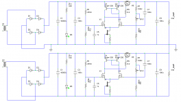
dual positive
Hi guys...
I have difficulty to find the same parts as you use.
Can I only use N channel mosfet, may I use
IRF540 or IRF2807
BS170 & K246 as CCS...
(the target output is 40 to 45VDC for now)
I modified the schematic & I think it is OK to try...
need some thought
Regards
John
Hi guys...
I have difficulty to find the same parts as you use.
Can I only use N channel mosfet, may I use
IRF540 or IRF2807
BS170 & K246 as CCS...
(the target output is 40 to 45VDC for now)
I modified the schematic & I think it is OK to try...
need some thought
Regards
John
Attachments
- Status
- This old topic is closed. If you want to reopen this topic, contact a moderator using the "Report Post" button.
- Home
- Amplifiers
- Power Supplies
- Finished capacitance multiplier