I put you down for 1 board, and you can always change your mind later.Is it correct that for a stereo VSSA (LC) amp +/- 35V, one PSU board is sufficient? In that case one PCB is sufficient for me. Else, Two Boards. Sorry for the misunderstanding.
--gannaji
In my opinion, w. 35V supply rails (which is what I am using), one power supply is enough, even at fairly loud listening levels, assuming a normal room, 8-ohm speakers, recommended bias, etc.
With a clean power supply, VSSA sounds exceptionally good, and does not require a huge amount of reserve power. This applies even to the very first and simplest version I built from Shaan's schematic. I tested the influence of the power supply, by comparing to an old adjustable linear bench supply from Tektronix. This led me to the capacitance multiplier approach.
If you expect to run your VSSA at the limits LC specified, or speakers which represent a "difficult" load, then you probably need two, as he recommends.
It basically comes down to how far the DC voltage will dip during heavy bass passages at high volume.
The other reason to use two separate supplies is if you have the kind of no-compromise sound system and listening room that LazyCat used in some of the VSSA tests. Using separate power supplies makes the two channels independent, so with the right listening room and very good speakers, it will enhance what people refer to as "soundstage", depth, separation of vocals from background music, etc. That kind of sound system takes a lot of money, or a lot of time, or both. I get speaker envy any time I look at the pics of his listening tests! (some of the speakers LC was testing with cost almost as much as my car...
 )
)Yes....a typo, sorryOne does not need PSU bypass.
Silmics II usually give strong bass in signal bypass and psu decoupling too... this is my personal experience only...
ciao
Here is a list of those showing an interest in the boards, so far. If you requested a specific quantity, it will be after your name. I meant to post this earlier, sorry. I plan to re-order boards around middle of next week. There are a few questions in my pm box I have not answered, but I will get to it in the next day or two.
Besides the BOM in pdf form posted above, there is a Mouser BOM with all parts I sourced from that distributor, being reviewed by a couple people this weekend.
IvanLukic(3)
Freeman(tbd)
Idefixes(tbd)
Touchdown(tbd)
vgeorge(2)
Merlin el Mago(2)
Jameshillj(2)
Jsixis(2)
Praudio(2)
Compressit(4)
Cambe(2)
Gannaji(1)
Potepuh(2)
Syklab(2)
Taking the reservoir capacitors directly back to an external star ground ensures that their charging current spikes don't contaminate the rest of the circuit. However, PMI's measurements demonstrate that you can get good results without going to such lengths, and using a single ground on the PCB means that his version doesn't need an external star ground....Curiously, Miles' original brds had a separate ground connection for the input power supply caps and another for the rest of the circuit's 0 volt points - not good?
I made the board layout so it can be used after a CRC or CLC supply as a filter, if larger caps are required for high current. The connections on the side, just before the fuses, are intended for an unregulated input (or output). The pass transistor can actually take quite a bit of current, if it is heatsinked well.I've found that in a low current application, the capacitor multiplier is OK, but in the high current environment nothing beats a decent CLC power supply.
This is also the reason why there is a place for an optional hf suppression cap near those connectors.
Having said that, my main goal was an inexpensive low ripple and low noise power supply for class A-B amps, similar to the two versions of VSSA I have.
Another idea that was suggested to me was to make a board with two parallel cap multiplier filters using MrEvil's circuit, and no rectifiers, and perhaps tweak some component values specifically so it can be used at higher currents, as a post-filter.
That would definitely be overkill for my original application, so it is hard to say how many people could actually benefit from that...
As already mentioned the output was very clean without the split grounds, but at the same time, I hope nobody will take that as an argument against star grounds, that is not my intent. I am happy with the results, no supply I have built for audio so far, has had such low noise and low losses in combination, at least not at power levels seen in a power amplifier.Taking the reservoir capacitors directly back to an external star ground ensures that their charging current spikes don't contaminate the rest of the circuit. However, PMI's measurements demonstrate that you can get good results without going to such lengths, and using a single ground on the PCB means that his version doesn't need an external star ground.
There is a ground return on the board for each take-off point (connector which is a source of current). The arrangement which this makes possible is that each power wire can be twisted together with its ground return (if desired), and the currents stay balanced in the twisted wires, within reason. This does not mean you have to do it this way, but the options are there. Nothing prevents taking all ground returns back to an off-board star ground.
I have seen this done in other (non-audio) critical applications with good success. There is a much better discussion of this and related issues in Bob Cordel's Book thread, here:
Half-Wave Rectified Currents
You have to read back from this post by Andrew, not sure where the discussion starts. "Half-wave" in this case refers to the current flowing alternately in the positive and negative rail as the output crosses the zero point, not the rectifier.
None of these approaches is a magic bullet, AFAIK, you have to pick the one relevant to your application. Measuring this is very difficult, so usually, one can at most observe or listen to the effect on the output, but not actually see or measure the source of the noise.
Last edited:
How did you find this?I've found that in a low current application, the capacitor multiplier is OK, but in the high current environment nothing beats a decent CLC power supply.
Just back from 10 days of vacation, I update the list with quantity (2) I'm interested in:
IvanLukic(3)
Freeman(tbd)
Idefixes(tbd)
Touchdown(2)
vgeorge(2)
Merlin el Mago(2)
Jameshillj(2)
Jsixis(2)
Praudio(2)
Compressit(4)
Cambe(2)
Gannaji(1)
Potepuh(2)
Syklab(2)[/QUOTE]
quan(2)
tjencks(2)
Thanks a lot
Nicola
IvanLukic(3)
Freeman(tbd)
Idefixes(tbd)
Touchdown(2)
vgeorge(2)
Merlin el Mago(2)
Jameshillj(2)
Jsixis(2)
Praudio(2)
Compressit(4)
Cambe(2)
Gannaji(1)
Potepuh(2)
Syklab(2)[/QUOTE]
quan(2)
tjencks(2)
Thanks a lot
Nicola
No problem guys - Feel free to add or subtract, I will make sure there are enough boards for everyone on the list when I place the order plus a few spares. Doing this informally saves me time
There seems to be an interest in a couple dozen boards, that is enough to reorder. I have one more test to run, and a few questions in my PM box to answer, which I promise to get to in a day or so.
The Mouser BOM is finished, but the way this is "shared" is when I enter your email address into a box on the Mouser web site. In other words, there is no way to "post" a link to that here... if I do not have your email address to plug in, you did not get the Mouser version, sorry.
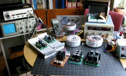
The pics below are just about everything used for testing, old Tektronix oscilloscope, signal generator, VSSA boards mounted on heatsinks etc.
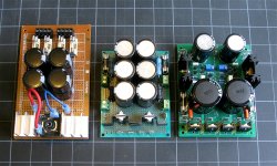
The second picture shows the two power supply versions used for comparison purposes. Left to right, a bridge rectifier and capacitor bank w. same value as the main rectifier filter cap on the new board. The CLCRC configuration, same total capacitance per rail as the Cap Multiplier board. On the right, MrEvil's Capacitance Multiplier.
There seems to be an interest in a couple dozen boards, that is enough to reorder. I have one more test to run, and a few questions in my PM box to answer, which I promise to get to in a day or so.
The Mouser BOM is finished, but the way this is "shared" is when I enter your email address into a box on the Mouser web site. In other words, there is no way to "post" a link to that here... if I do not have your email address to plug in, you did not get the Mouser version, sorry.
The pics below are just about everything used for testing, old Tektronix oscilloscope, signal generator, VSSA boards mounted on heatsinks etc.
The second picture shows the two power supply versions used for comparison purposes. Left to right, a bridge rectifier and capacitor bank w. same value as the main rectifier filter cap on the new board. The CLCRC configuration, same total capacitance per rail as the Cap Multiplier board. On the right, MrEvil's Capacitance Multiplier.
Attachments
Capacitance Multiplier filter during Bass passage
I thought I would post this one test result as it relates to a discussion elsewhere. This is one reason why I was interested in using MrEvil's Cap Multiplier with VSSA, and later I hope other similar circuits.
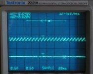
The first pic shows the power supply ripple before (top trace) and after (bottom trace) the cap multiplier and pass transistor, in other words at the main filter cap (top) and output of the supply (bottom).... during a quiet passage w. little bass content.
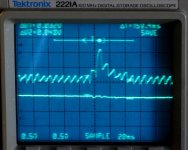
The second pic shows the same, but during a passage with moderate/heavy bass. Top trace is before the cap multiplier pass transistor. Bottom trace, after the pass transistor, at the output of the supply. Without the cap multiplier, noise boosted by LF transients easily exceeds 4x the ripple voltage.
In the second picture, you can see the ripple riding on top of what is a single transient, about 40-50 msec long, or 20Hz frequency. The lower trace shows that the capacitance multiplier is effective in suppressing even sizeable LF transients. (not necessarily every cap multiplier will do that, it depends on the time constant of the RC circuit, but this one will, and quite well) At the output of the power supply, there is barely a trace.
The material used for the test is just what I happened to be listening to this morning, David Benoit, Shadows, track 5. Fairly easy listening, new-age-ish music to have w. morning coffee...)
The power supply was not loaded externally, like some of my other tests, so the ripple represents normal load plus standing current. Dropout voltage was set at 0.8V, and the volume was turned up to moderately loud, I would say 3-6 db above my normal single-room listening level. DC rail voltage adjusted to 35V after the cap multiplier using variac. Oscilloscope on digital storage mode. Vertical resolution 0.5V per division, standing current ripple under these conditions is about 200-250mV.
I thought I would post this one test result as it relates to a discussion elsewhere. This is one reason why I was interested in using MrEvil's Cap Multiplier with VSSA, and later I hope other similar circuits.
The first pic shows the power supply ripple before (top trace) and after (bottom trace) the cap multiplier and pass transistor, in other words at the main filter cap (top) and output of the supply (bottom).... during a quiet passage w. little bass content.
The second pic shows the same, but during a passage with moderate/heavy bass. Top trace is before the cap multiplier pass transistor. Bottom trace, after the pass transistor, at the output of the supply. Without the cap multiplier, noise boosted by LF transients easily exceeds 4x the ripple voltage.
In the second picture, you can see the ripple riding on top of what is a single transient, about 40-50 msec long, or 20Hz frequency. The lower trace shows that the capacitance multiplier is effective in suppressing even sizeable LF transients. (not necessarily every cap multiplier will do that, it depends on the time constant of the RC circuit, but this one will, and quite well) At the output of the power supply, there is barely a trace.
The material used for the test is just what I happened to be listening to this morning, David Benoit, Shadows, track 5. Fairly easy listening, new-age-ish music to have w. morning coffee...
)The power supply was not loaded externally, like some of my other tests, so the ripple represents normal load plus standing current. Dropout voltage was set at 0.8V, and the volume was turned up to moderately loud, I would say 3-6 db above my normal single-room listening level. DC rail voltage adjusted to 35V after the cap multiplier using variac. Oscilloscope on digital storage mode. Vertical resolution 0.5V per division, standing current ripple under these conditions is about 200-250mV.
Attachments
Last edited:
No exotic parts. This is with the first board I built. I ran short of time building the second one, so this is w. close to the least expensive parts I found at Mouser.That's a pretty impressive result, Pete, and this is without any exotic parts at all?
Parts from reputable sources, but general purpose filter caps, diodes, etc. Output cap is a 4700uF electrolytic I bought in small q. from another member here for around $1.25 each, input cap is a 10,000uF made by CDE (SLPX103M063H7P3), around $5, rectifier diodes are the generic Schottky diode we already discussed. Rest is as per my BOM.
(This is not to say that a better-grade output cap would not help at mid-high frequency...
)- Status
- This old topic is closed. If you want to reopen this topic, contact a moderator using the "Report Post" button.
- Home
- Amplifiers
- Power Supplies
- Finished capacitance multiplier