Yes, I will have a Mouser BOM which covers most parts (all semiconductors & caps). I am already planning on shipping the jfets with the boards if necessary.... Based on looking at Mr Evils original component choices, all parts seem readily available as documented except jfets. When you finish testing, can you share some of your BOM choices with us?...
The board has a couple holes for a CRD to use instead of a jfet, but this too would add cost ($2 each, instead of $0.50 each for the jfets).
I have not posted a final schematic or BOM in case of changes. My original schematic had a couple errors and typos, and like most people, I prefer to fix my mistakes b/f anyone else can see them...
")
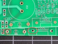
I think I have 5-6 spare boards from the original batch in addition to what I need for testing, or already promised to others. I will have to drill two sets of holes out for anyone who wants them now, as opposed to waiting for the next batch. Drilling these by hand is not as easy as it may seem, doing it on a drill press is much easier.
Attachments
I will post my take on this in more detail, later.Pete,
What would be the best choice of rectifier diodes for this kind of capacitance multiplier? I ordered MUR860, but I am a bit perplexed: ultra fast, fast recovery, soft recovery, Schottky....
In general I am in favor of using a soft recovery diode and a bigger heatsink, but bigger heatsinks and soft recovery diodes add cost, and I am trying to keep that low.
This is not so much a compromise, because you can choose a more expensive diode, and a better heatsink, or heatsink to the chassis (not my favorite, but I did design for this, and it can be done). At a guess, $4-6 additional cost incl. diodes & heatsink, for the best combination, over the most general purpose Schottky diode and ebay heatsink.
I am willing to add a couple extra holes to the board for a snubber, but someone else will have to suggest some component values. When I tried this in the past, the benefits were not so clear, meaning, visible on the scope, but not audible.
Drilling these by hand is not as easy as it may seem, doing it on a drill press is much easier.
I have a (cheap Chinese) drill press.
I'm not Pete, but will add my 2 cents ...
One of the 'softest/quietest' diodes that's readily available is the OnSemi MSR 860 or bigger brother MSR 1560, both TO220 packages.
Another one is the BYV29 - needs a decent heatsink for heavier currents (NOT the BYWs)
Actually, many people have used the MUR860 with excellent results and I found the addition of a basic RC snubber across the secondary windings to be also beneficial.
Local shop has IXYS DSEI8-06A (8A/600V FRED) which is probably just as good or even better than MUR860.
Rectifier diode choices and selection
Forward voltage drop:
Schottky diodes typically have lower voltage drop and generate less heat. The power dissipation in the bridge will be almost proportional to the forward voltage drop of the diode. This is the type of diode I am using for testing.
The mechanism used to achieve low forward voltage drop (I think it is called "increased injection") works against fast recovery. Increased injection means more charge has to be drained off b/f the diode stops conducting, so reverse recovery time goes up.
Fast recovery:
This is more important at high switching frequencies, like what you get in some consumer products designed to meet stringent power efficiency requirements. At switching frequencies >100 KHz , it can make a big difference. Not as much when switching line frequency, in my opinion. Sub 100ns switching times mean little when a diode turns on and off once at 50-60Hz.
The tradeoff is that fast recovery, by definition, means a more abrupt cessation of current, and that will generate more noise. Some of this will be removed in the power supply, but the noise radiated from the transformer and the transformer secondary leads, may be hard to get rid of completely.
Soft Recovery:
Soft recovery diodes will generate much less noise, and I am not even sure that a snubber would be required in this case, although in general it would help.
On the downside, the forward voltage drop can be about double compared to a general purpose Schottky diode. The MSR860 will have about 1.1 Vf at 5 Amps. At that current, an MBR10T100 has a forward voltage drop around 0.6V.
Heatsink:
The rectifier diodes should be heatsinked to allow for at least some intermittent high current demand. The circuit board is laid out for a small and inexpensive heatsink, but larger heatsinks are possible. I will post some pics in a day or two to show what this would look like, even though I do not think bigger heatsinks are required for VSSA variants, or for similar class A-B amplifiers.
The "increased injection" thing doesn't apply to Schottky diodes, as their operation is based on a different principle to PN junction diodes. Schottky diodes have no reverse recovery time at all, making them much, much faster than normal diodes. Their downside is high reverse leakage current. I tend to use Schottky diodes a lot myself because I value efficiency.Forward voltage drop:
Schottky diodes typically have lower voltage drop and generate less heat. The power dissipation in the bridge will be almost proportional to the forward voltage drop of the diode. This is the type of diode I am using for testing.
The mechanism used to achieve low forward voltage drop (I think it is called "increased injection") works against fast recovery. Increased injection means more charge has to be drained off b/f the diode stops conducting, so reverse recovery time goes up...
Great, & thanks for the correction!The "increased injection" thing doesn't apply to Schottky diodes, as their operation is based on a different principle to PN junction diodes...
Do you have any comments on using something like the MSR860 v. the generic Schottky diode?
I see that MSR860 is rated at 600V. Schottky diodes with such high voltage ratings are rarer and more expensive, and the forward voltage drop tends to be closer to that of a normal diode. Also, as PSU voltage increases, the losses from the diode's forward voltage drop become relatively smaller, so the advantage of a Schottky diode is less. Not that a 600V rating is necessary for this PSU, but it is still the case that Schottky diodes are more advantageous at lower voltages....Do you have any comments on using something like the MSR860 v. the generic Schottky diode?
My only experience with Schottky diodes was when I changed (for experiment) ordinary silicon diodes in analog section PSU of my Marantz CD57 Mk2 with SB160 Schottky diodes. The change of sound was incredible, much, much more resolution, speed and transparency, but, unfortunately, also less weight in low end. That was the only mod on that CD I ever made so it was easy to notice subjective differences in sound. I must admit that I liked that mod, meaning "the sound of" Schottky diodes in PSU.
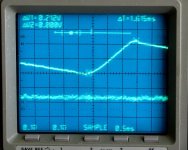
@jameshillj: So far I do not see any sign of ringing at the turnoff time for the Schottky rectifier diodes I am using currently. That does not mean it is not there, but at least after the recifier, at the node where the main filter cap is connected, nothing.
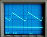
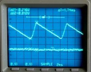
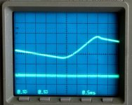
There is a small amount of overshoot in the ripple waveform, but no hf ringing.
The pics were taken at idle, and show around 200 mV ripple before the filter (upper trace), and essentially zero after the filter (lower trace). The result is about the same at higher power, I tested up to about 2A load.
The random noise seen when the scope is on digital storage setting has more to do with my wiring and test conditions.
Attachments
@Triodethom: I think your comment may have been for Ivan, but for what it's worth... For the moment, I am using pretty generic electrolytic caps for testing, along with other low-cost parts.
One of the goals was to find a power supply that would fit well with the lower cost implementations of LazyCat's VSSA, and still provide clean power, free of most ripple or noise. (Or, other similar, class A-B designs, that can benefit from an inexpensive filtered power supply).
Although at first glance MrEvil's circuit looks like overkill, the components are inexpensive. The incremental component cost is about $15, compared to a power supply with the same total filter capacitance (~15000uF). That is about the cost of adding another pair of large filter caps, and the circuit takes up about as much board space (!).
Another consideration was building the filter circuit with components very close to those chosen by the OP. Basically, when I use someone else's design, I try to build it the way he intended, at least in the beginning...
Having said all that, I am not at all against suggestions for improvements, or more costly parts, just not the first step out the door...
Yes, same heatsinks.Are you still using the same heatsinks on the pass devices as post #32?
Curious about how long you ran this at 2A, and how that size heatsink is performing in general.
The reason for the questions, I am thinking about giving this a go on an F5 amp biased @ 1.6A
I ran it for a while, but not long enough, and in free air, not in a closed box.
Ultimately, the answer to your question will depend on the forward voltage drop of your preferred rectifier diode, and on how high the dropout voltage at the pass transistor must be set.
However, I DID design the board for much higher sustained current than what I will ever see with my class A-B amps, in part b/c I had a request to do that from a friend.
I will show some pics of what that will look like in a couple days, and it will still be moderately inexpensive (did I say I was cheap?... yeah, I am pretty sure I did...
)Thanks Pete for going to the trouble with the diodes on #75.
It looks like there's not much point in adding the extra snubber components after all, which is a bonus, and anyway, easy enough to add them underneath later on.
Would there be any benefit in adding a small series resistor in series between the diodes and the first (ripple) cap, if that could be easily tried?
In 'normal' C multipliers, like the ones for the Aleph amps with IRFPs, etc, it does make a difference to the sound, even with softer diodes but with this design, it may again be unnecessary.
Ultimately, the answer to your question will depend on the forward voltage drop of your preferred rectifier diode, and on how high the dropout voltage at the pass transistor must be set
I am dual secondarys at this point, and will be looking to splice in post rectifier for the CM benefits initially.
- Status
- This old topic is closed. If you want to reopen this topic, contact a moderator using the "Report Post" button.
- Home
- Amplifiers
- Power Supplies
- Finished capacitance multiplier