
@touchdown:
Thanks for the compliment and your interest... of course, remember that all the original work was done by MrEvil, who is kindly sharing his design w. the rest of us...
I have seen this type of regulation before, just not in audio, which gives me some confidence that this will work out well.
VSSA (which is why I started on this), definitely sounds better with a clean supply. I have tested with a couple conventional power supply configurations, and with a large Tektronix linear bench supply. The difference is small, but noticeable in a controlled a-b test. More so with better speakers...
In General:
I have a few spare boards from the initial batch of ten, and I can always reorder, if there is an interest.
Electrical and noise testing looks good so far, but I am not done yet.
Ripple and rectifier noise is below measurable levels. In the presence of 10-15mV of HF noise from radio etc., and on my old 100MHz Tektronix 2221A, with conventional 10-x probes, I cannot measure below 20mV.
I have found three small mechanical problems, two with incorrect hole size, and one was a plain error on my part, w. hole spacing. The incorrect hole size is an indirect result of getting boards at a discount. Normally there is a tooling charge of >$100 per order. Without this, they basically run whatever you send them. And, my drill file did not translate cleanly. As a result, two large hole sizes defaulted to the smallest size specified.
Availability:
If all works out well, I will definitely re-order, so if you are reading this, you won't miss anything if you don't get a board from the first batch. It will just take an extra 2-3 weeks. To get boards at a decent price, I can't specify lead times less than 2 wks, or less than 3-5d shipping.
A GB may not make sense. I am willing to look into it, but: As long as we operate under a discount, there is little cost savings until about quantity 100 (without the discount, sure, a GB is a good deal). At the same time, the first people showing an interest have to wait the longest time, which does not seem fair to me. So, not sure if it is worth it to save $1-2 per board.
@Merlin the magician - for delivery to a "future state in Europe", you must use your own special powers, the rest of us mortals are a bit limited in that regard, as follows...
Recent experience has shown that small pkg (or padded envelope) delivery to CE countries may take up to two weeks... Cost by regular mail in a padded envelope to Europe is as follows:
2oz (1 board): $2.90
3oz (2 boards): $3.75
4oz (3 boards): $4.60
5oz (4 boards): $5.45
One board can probably be mailed in a regular envelope w. a 'Non-machinable" surcharge (rigid contents), for $2.25.
Recent experience has shown that small pkg (or padded envelope) delivery to CE countries may take up to two weeks...
Cost by regular mail in a padded envelope to Europe is as follows:2oz (1 board): $2.90
3oz (2 boards): $3.75
4oz (3 boards): $4.60
5oz (4 boards): $5.45
One board can probably be mailed in a regular envelope w. a 'Non-machinable" surcharge (rigid contents), for $2.25.
I have a few from my original order that are not already spoken for. If there is enough interest, I intend to order another batch.I am not in a hurry, so kindly let me know when you are going to have some boards available.
As for shipping, a few bucks more or less is not a big difference.
I intend to use them on a VSSA too.
Basic testing is done, the boards work, most of my remaining testing is to make sure that the selected resistor values are correct, where to set the dropout voltage, and measuring a few parameters so other people can compare results. I plan to finish testing this weekend.
Two sets of holes on the original boards have to be drilled out to fit. I plan to do this for any I send out.
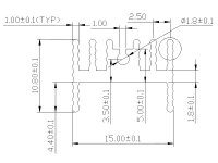
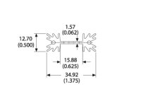
TO-220 Heatsink sizes and specifications
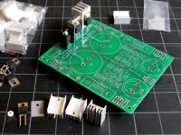
The heatsinks were chosen for low cost. 4 of the smaller type for rectifier diodes, and two of the larger type for the pass transistor are required, total cost around $3-$4 for all six heatsinks.
The smaller heatsink footprint is 10mm deep x 15mm wide, 21-25mm in height, with a single hold-down pin that can be soldered to the board. It is a type available from various sources on the internet, ebay etc. starting at around $0.30/each.
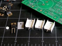
Other similar heatsinks can be substituted up to 20-mm wide. One of the pictures below shows a couple alternatives I happened to have on hand. There is nothing unique or special about the one I chose, I simply happen to like it (and, low cost).
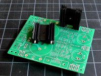
The larger heatsink is used for the pass transistor, and is a standard type available from any distributor such as Mouser, for about $1. In the picture it is a Thermaloy 513102B02500G, rated at 11C/Watt. This is a bit more critical, and is chosen to be larger than needed for a typical class A-B amplifier. Going too cheap here, means that the dropout voltage cannot be adjusted over its full useful range. There are 3 or 4 different heights available, as well as similar heatsinks which will fit the same space.
If there is enough interest in the circuit board to warrant another order, I will do my best to keep a few sets on hand.
The heatsinks were chosen for low cost. 4 of the smaller type for rectifier diodes, and two of the larger type for the pass transistor are required, total cost around $3-$4 for all six heatsinks.
The smaller heatsink footprint is 10mm deep x 15mm wide, 21-25mm in height, with a single hold-down pin that can be soldered to the board. It is a type available from various sources on the internet, ebay etc. starting at around $0.30/each.
Other similar heatsinks can be substituted up to 20-mm wide. One of the pictures below shows a couple alternatives I happened to have on hand. There is nothing unique or special about the one I chose, I simply happen to like it (and, low cost).
The larger heatsink is used for the pass transistor, and is a standard type available from any distributor such as Mouser, for about $1. In the picture it is a Thermaloy 513102B02500G, rated at 11C/Watt. This is a bit more critical, and is chosen to be larger than needed for a typical class A-B amplifier. Going too cheap here, means that the dropout voltage cannot be adjusted over its full useful range. There are 3 or 4 different heights available, as well as similar heatsinks which will fit the same space.
If there is enough interest in the circuit board to warrant another order, I will do my best to keep a few sets on hand.
Attachments
I have a few from my original order that are not already spoken for. If there is enough interest, I intend to order another batch.
Basic testing is done, the boards work, most of my remaining testing is to make sure that the selected resistor values are correct, where to set the dropout voltage, and measuring a few parameters so other people can compare results. I plan to finish testing this weekend.
Two sets of holes on the original boards have to be drilled out to fit. I plan to do this for any I send out.
We are waiting to finish your testing then!
No problem for me regarding the holes.
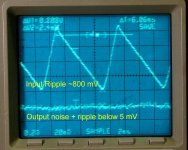
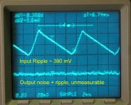
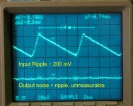
Test Results, Capacitance Multiplier as Ripple Filter
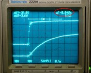
The following three pics show the voltage waveform at the input (top trace) and output (bottom trace) of the pass transistor on the power supply, at about 270 mA, 600 mA, and 1.25A steady current draw.
270 mA is representative of the standing (quiescent) current at the typical settings for LC's VSSA modules, two channels, and also the most common variants, like Shaan's PeeCeeBee version, and my through-hole VSSA boards. This is significant b/c the first goal of adapting MrEvil's circuit was to provide a clean linear power supply as an alternative to using the recommended SMPS (which of course has zero ripple by definition).
Test Conditions:
AC line input adjusted through a Variac for +/-35V DC nominal (34.5 actual), at the cap multiplier output.
Main filter caps, 10,000uF, 63V
Dropout voltage adjusted to ~1V using the trim pots on the power supply
Output caps, 4,700uF, 63V
Incandescet lamps were used as load, 120V/60W, 120V/125W, 120V/250W
Fluke 77 multimeter, Tektronix 2221A digital storage scope
Besides essentially zero ripple, I saw no signs of switching noise from the rectifier diodes at the output of the power supply, which was very encouraging for VSSA and its variants (very wide frequency range).
Attachments
Test Results, Startup and Shutdown
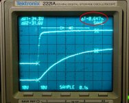
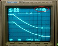
One of my goals was a slow and controlled start, compared to rectifier/filter alone, and compared to other alternatives. The pics below show the rise time before the pass transistor and cap multiplier circuit, after the pass transistor (the output of the power supply), and the third pic shows the shutdown.
The startup shows a small notch at low voltage, but is otherwise smooth and gradual. There is no audible startup noise from the speakers. There is also no shutdown noise, unless the source is still playing.
These tests were using the amp as a load, so they represent results at ~300mA idle current.
Overall, I would say so far everything seems to work as described by MrEvil at the beginning of this thread.
Attachments
Last edited:
Hi Marc,Hi Pete,
Do to results i thinks goal is reached...
Marc
Yes, functionally, I am sure now it does what I had hoped.
I am very happy, less than 10mV at idle, including ripple and noise is much better than anything else I have tried...
I still have to look at the temperature rise at the heatsinks, and make sure I know at what point you have to increase heatsink size. I made sure there are options for heatsink size and vendor, and mounting from under the board, but I have no actual temp measurements yet.
For VSSA or PeeCeeBee version, or my through hole version with +/-35V rail voltage, the component values are correct. For maximum power as specified by LazyCat and by Shaan, at 45V rails, the main reservoir cap should be increased for best performance (15,000-22,000uF), and the pass transistor heatsink to the next size/height, or dual PSUs (which LC recommends anyway).
For amplifiers with a bias current which is significantly higher than VSSA, attaching the rectifier diodes and the pass transistors to a common heatsink will be the best solution. (A simple aluminum or copper plate will probably do fine).
P.
I'm not Pete, but will add my 2 cents ...
One of the 'softest/quietest' diodes that's readily available is the OnSemi MSR 860 or bigger brother MSR 1560, both TO220 packages.
Another one is the BYV29 - needs a decent heatsink for heavier currents (NOT the BYWs)
Actually, many people have used the MUR860 with excellent results and I found the addition of a basic RC snubber across the secondary windings to be also beneficial.
Wow. You can count me in for 4 boards as you plan future orders.
Based on looking at Mr Evils original component choices, all parts seem readily available as documented except jfets. When you finish testing, can you share some of your BOM choices with us?
Mr Evil thanks for sharing your circuit, and PMI thanks for your follow up work and board.
Based on looking at Mr Evils original component choices, all parts seem readily available as documented except jfets. When you finish testing, can you share some of your BOM choices with us?
Mr Evil thanks for sharing your circuit, and PMI thanks for your follow up work and board.
- Status
- This old topic is closed. If you want to reopen this topic, contact a moderator using the "Report Post" button.
- Home
- Amplifiers
- Power Supplies
- Finished capacitance multiplier