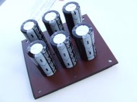
A lot depends on what parts of the noise spectrum you are trying to reduce. There will not be a single best answer. If you are most concerned about the mains ripple, a couple thicker wires, or strips of copper foil, will work just fine. This is what most people are trying to do with big cap arrays anyway....The capacitors are mounted to a two sided copper clad board and this was shown to be superior to a point to point wiring layout. ...
For the rest, there is no substitute for a double-side circuit board with a decent layout, and a handful of other small parts. A copper-clad board is part-way there, and it can be fun to carve the tracks yourself. But you can't replace a good layout (not like the boards offered in the "store" section, or other versions. And for another thing, using multiple numbers of a single size electrolytic cap does not seem to give the best results, you would have to combine large and small caps, etc, etc...
The mosfets, ZVN2106A and ZVP2106A are both again in stock at Mouser. So, no need for replacements, unless someone needs a higher voltage part.
Hi Pete, do you know what would be neat : a little board with possible parts function rail/Amp voltage...so respond to all question about it.
Marc
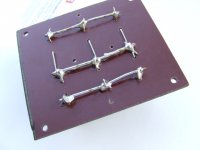
I prefer to hardwire. This allows close coupling of the wiring and even twisting on EVERY connection.
Andrew, do you have a photo illustrating this? I'm picturing two rows of capacitors, with twisted pairs of insulated wiring connecting the +ve and -ve terminals with the adjacent capacitor(s) in each row.
If this is what you have in mind, how do you propose to connect the terminals of each filter bank such that both power rails share a common ground plane? Are ground loops an issue with this arrangement?
I usually use blank board (without copper) and drill the necessary holes. With wired caps I use tinned solid core copper wire for connection between caps. With the bank on the pic ground wire should ideally be exactly in the middle between negative and positive, but I wanted space around caps for better cooling inside completely closed chassis, so there was not enough cap wire for that.
Attachments
Inrush Current and Fuse Rating
The following is with reference to the earlier discussion about inrush current, closely rated fuses, and whether an external soft-start circuit may be required.
Suggestions, comments, and snide remarks are all equally welcome...
I repeated some of my earlier tests with what I hope are better test conditions, this time with only one transformer size, one fuse, and paying more attention to the scope trigger...
I plan to do a few more tests with other transformers, but it may take a few days. In the meantime, most of the second PCB order is likely to arrive in the hands of people who are building power supplies... So, I would appreciate it if someone could do a sanity check on my assumptions and first test results, and perhaps pick up where we left off.
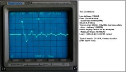
The first test was run with a transformer size and fuse rating which roughly corresponds to 60W per channel. Results still seem to indicate no requirement for an external soft start, at least not with the Cap Multiplier at the loads and with the size of reservoir caps I expect for a class A-B amp up to 100W, even if a "closely rated" fuse is used.
This assumes a slow-blow chassis fuse. If you like using fast-blow line fuses, your mileage (and number of charred fuses) will definitely vary... tested
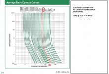
The results seem to indicate that the peak inrush is around 25A for 4 milliseconds, and diminishes quickly after that. The limit for the slow-blow fuse I am using for the test is about 50A for 10 milliseconds, and at 25A about 30 milliseconds.
Another way to look at this is that it would take 8 "shots" at this inrush current to activate a closely rated slow-blow fuse. I am not very good at doing integration off an oscilloscope screen shot, but it looks to me like we have only between 15 and 25% of fuse activation before the current settles.
I have 400, 500, and 600VA transformers on hand to run some more tests, but as I said, it will take a little time.
The following is with reference to the earlier discussion about inrush current, closely rated fuses, and whether an external soft-start circuit may be required.
Suggestions, comments, and snide remarks are all equally welcome...
I repeated some of my earlier tests with what I hope are better test conditions, this time with only one transformer size, one fuse, and paying more attention to the scope trigger...
I plan to do a few more tests with other transformers, but it may take a few days. In the meantime, most of the second PCB order is likely to arrive in the hands of people who are building power supplies... So, I would appreciate it if someone could do a sanity check on my assumptions and first test results, and perhaps pick up where we left off.
The first test was run with a transformer size and fuse rating which roughly corresponds to 60W per channel. Results still seem to indicate no requirement for an external soft start, at least not with the Cap Multiplier at the loads and with the size of reservoir caps I expect for a class A-B amp up to 100W, even if a "closely rated" fuse is used.
This assumes a slow-blow chassis fuse. If you like using fast-blow line fuses, your mileage (and number of charred fuses) will definitely vary... tested
The results seem to indicate that the peak inrush is around 25A for 4 milliseconds, and diminishes quickly after that. The limit for the slow-blow fuse I am using for the test is about 50A for 10 milliseconds, and at 25A about 30 milliseconds.
Another way to look at this is that it would take 8 "shots" at this inrush current to activate a closely rated slow-blow fuse. I am not very good at doing integration off an oscilloscope screen shot, but it looks to me like we have only between 15 and 25% of fuse activation before the current settles.
I have 400, 500, and 600VA transformers on hand to run some more tests, but as I said, it will take a little time.
Attachments
I read your earlier post, and I was surprised the fuse blew. It's one reason why I ran the tests again.Hi Peter ,with my set up 2 of 300 VA transformer - 2 A slow blow fuse did not survive start-up. Now i use a soft start with 1.5A F fuse without any problem. My be i should get 1A fuse for closer rating .
Quan
I would keep the 1.5A. 1A fuse at 220V AC would only give you ~220VA x 0.9, divided between two toroids. That would allow a little less than full volume power, I think. That is less than it should be, unless I am screwing up the math.
At 110V, 300VA would require 3~3.5A slow-blow at full power. At 220V, the primary windings are in series, so the steady-state current is half at the same VA. However, the core is still the same size. I am testing at a light load, so I assume the inrush is before the core is fully magnetized. I am not sure if the inrush current is in proportion to the steady-state current, so it is possible a 2A fuse was under-rated for inrush for two toroids. It might be close.
I plan to test at 400 or 500VA next, and see how it goes.
Hi Peter ,with my set up 2 of 300 VA transformer - 2 A slow blow fuse did not survive start-up. Now i use a soft start with 1.5A F fuse without any problem. My be i should get 1A fuse for closer rating .
Quan
Quan,
What kind of soft start you are using with these two transformers? Frankly, I do not think that for VSSA two 300VA transformers are necessary.
I think there is still something here I am missing, but in any case you have everything running well now, and without a huge fuse, which is after all the most important part.Hi Ivan, i used one of soft start kit from ebay. I know two transformers may be over kill but my speakers are a hard load.
Quan
Hi Ivan, i used one of soft start kit from ebay. I know two transformers may be over kill but my speakers are a hard load.
Quan
No matter how big transformers you use, you shall always be limited by the rails voltage. In your case VSSA (with Latfet outputs) will not be able to output more than 50W/8Ohm from 35V rails even if you transformers are 1000VA each! And these 50W will be your limit to drive any loudspeaker with highly reactive components. The only possible reason to use big transformers is to be sure that they will survive extreme misuse: 24/7 work at clipping power. I hope that you don't intend to go that far. And if you don't intend to go that far you only complicated your life with two big transformers for 50W-er. You only created inrush issue without any need for it.
A little more than that. I assumed it was around 50~55W, but LC corrected me, and when I looked at my measurements I saw he was right.No matter how big transformers you use, you shall always be limited by the rails voltage. In your case VSSA (with Latfet outputs) will not be able to output more than 50W/8Ohm from 35V rails...
@Ivan, Quan:
There are some numbers in recent posts in the main VSSA thread on max power that may be helpful.
The VSSA datasheet from LazyCat's modules states +/-45V DC absolute maximum, and also, "100 Wrms/8 Ohm max". This is consistent with where I measured clipping, or about 4V below the rails.
For what it is worth, some measurements (same boards Ivan has, but w. Renesas Latfets, at about +/-35V supply voltage):
Supply Voltage: ~+/-35.2
Input Signal: 1KHz
Max undistorted output: ~62Vp-p, or 31Vpk
Max clipping output: ~64Vp-p, 32Vpk
Max calculated power: 60~64 W per channel into 8 ohms
Average current: 2.8A
Someone can do a sanity check on my numbers, and recalculate for Quan's actual speaker load. I started with the pics below, which I consider to be the maximum un-distorted signal, and a typical clipped output.
For my money, and assuming well-behaved 8-ohm speakers, a single 300VA/25V transformer is enough (with this supply). Since I do not normally listen at very high levels, even a 250VA is plenty with any highly filtered supply. (I do some of my testing with 400~500VA, and up to 50V rails, anticipating what other people may use)
I feel like I am still missing a piece of the picture with the max power, the inrush, and the fuse ratings. I have re-read all the posts, including by AndrewT, and someone will have to throw me a bone here...
Attachments


Hi quan, ivanlukic, and PMI, exiting reading to learn from and all seems right.
Another angel is source to load relationship is speedier in quan setup i guess. Load for quan's mains transformer is only one CM verse two, this gives more speed/dynamic/linearity especially for lows i think. So when we send a constant full wide audioband signal thruu quan's setup instead of fixed test sinus signal, i guess there is difference especially at loud listening levels in lows. And if primary capacitor in CM is choosen to be bigger like the one Idefixes use, also lower source impedance from mains trafo would be advantage. This is probably not needed for everyday listening, but if he wan't to go more high end it could be right, and here 500VA/1000VA simetimes are choosen. Am i wrong ?
Another angel is source to load relationship is speedier in quan setup i guess. Load for quan's mains transformer is only one CM verse two, this gives more speed/dynamic/linearity especially for lows i think. So when we send a constant full wide audioband signal thruu quan's setup instead of fixed test sinus signal, i guess there is difference especially at loud listening levels in lows. And if primary capacitor in CM is choosen to be bigger like the one Idefixes use, also lower source impedance from mains trafo would be advantage. This is probably not needed for everyday listening, but if he wan't to go more high end it could be right, and here 500VA/1000VA simetimes are choosen. Am i wrong ?
It is well known fact that Lateral mosfets, especially only one output pair of single die Latfets, prefer higher and stable loudspeaker impedance. Therefore, VSSA in its basic form (one output pair of single die latfets) is not best suited for very difficult loads. For such speakers one needs higher current capabilities in output stage of amp meaning more output transistors in parallel. So, there is not much point in increasing transformer specs before output stage is enhanced. Quan's PSU setup would show it's true abilities only after such upgrade. It's possible that quan's PSU will shine with new versions of VSSA with improved output stage and only than will it be truly suited for reactive loads.
A little more than that. I assumed it was around 50~55W, but LC corrected me, and when I looked at my measurements I saw he was right.
@Ivan, Quan:
There are some numbers in recent posts in the main VSSA thread on max power that may be helpful.
The VSSA datasheet from LazyCat's modules states +/-45V DC absolute maximum, and also, "100 Wrms/8 Ohm max". This is consistent with where I measured clipping, or about 4V below the rails.
For what it is worth, some measurements (same boards Ivan has, but w. Renesas Latfets, at about +/-35V supply voltage):
Supply Voltage: ~+/-35.2
Input Signal: 1KHz
Max undistorted output: ~62Vp-p, or 31Vpk
Max clipping output: ~64Vp-p, 32Vpk
Max calculated power: 60~64 W per channel into 8 ohms
Average current: 2.8A
Someone can do a sanity check on my numbers, and recalculate for Quan's actual speaker load. I started with the pics below, which I consider to be the maximum un-distorted signal, and a typical clipped output.
For my money, and assuming well-behaved 8-ohm speakers, a single 300VA/25V transformer is enough (with this supply). Since I do not normally listen at very high levels, even a 250VA is plenty with any highly filtered supply. (I do some of my testing with 400~500VA, and up to 50V rails, anticipating what other people may use)
I feel like I am still missing a piece of the picture with the max power, the inrush, and the fuse ratings. I have re-read all the posts, including by AndrewT, and someone will have to throw me a bone here...
Hi PMI,
Just my simple curiosity, first small track is the vcc rail?
not understand well (if yes) how follow the power in opposite way

maybe i have ..smoking
The 35V rail is not shown. The test was done with the Cap Multiplier power supply, so the rail is perfectly flat. (I did not have time to take new pics, so I used a couple pics I already had).Hi PMI,
Just my simple curiosity, first small track is the vcc rail?
not understand well (if yes) how follow the power in opposite way
maybe i have ..smoking
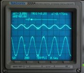
Channel 1 of the oscilloscope and delta v1 is the input signal, directly from the signal generator. (The scope is old, and when using the digital memory setting, the signal does not look perfectly smooth). The rail voltage was adjusted to 35V for this test, and from my notes, it was actually 35.2V for this particular test, because it can vary a bit with line and load variation.
Channel 2 is the output of the amplifier.
In the first picture I adjusted the input to get the highest output that I would consider to be un-distorted. This is a bit less than actual clipping. (As far as I am concerned this is a good thing, because the transition from a clean signal to a clipped signal is extremely good for such a simple circuit). The ratio between v1 and v2 gives you the approximate gain of the circuit (exact gain measurement can't be done on this scale with my equipment, so the number is off a few %)).
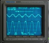
In the second picture, you see the actual clipping, and delta v2 shows the maximum peak-to-peak output of the amplifier (with the Renesas Latfets), at +/-35.2V. The difference between the rail voltage and the clipped output is:
35.2 - (64/2) ~ 3.2V (I measured 3.5 in other tests)
The difference between the rail voltage and max undistorted output is:
35.2 - (61.6/2) ~ 4.4V
So, max power at 35V rail voltage is ~64W, or ~60W depending on your definition. It can be more, or less, depending on the line and load regulation of the power supply.
Attachments
Channel 1 of the oscilloscope and delta v1 is the input signal, directly from the signal generator.
Does this mean that VSSA needs 3V input for max output? If so, that's very low input sensitivity, isn't it?
- Status
- This old topic is closed. If you want to reopen this topic, contact a moderator using the "Report Post" button.
- Home
- Amplifiers
- Power Supplies
- Finished capacitance multiplier