The truth is active regulation of the whole power amp (front and back-end) is just as complicated as driving one amp with another. Because I am having my transformers custom wound (it cost the same as off the shelf) I’m going to have them wind the two secondarys wit taps at 0-40-50Vac. This will give me two rails, one at +-57Vdc and one at +-70Vdc. The 70volt rails can be regulated down to 57v. If the active regulation doesn’t make things sound better I just chuck the boards and go with no regulation by using the 57v tap from the transformer.
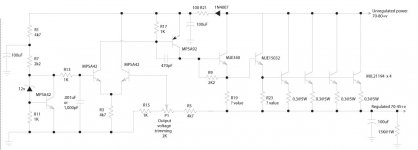
The Anthony Holton regulator witch is an improvement on the Ryan Power Voltage Regulator seems best to me. I would like to get more power out of it. I have taken the hard to read picture and redrawn it with some changes.
Changes:
Replaced all 2SC2240 with MPSA42
Replaced all 2SA970 with MPSA92
Replaced all power devices with MJL21194 and MJL21193
Doubled the number of output devices
Renumber all resistors
I have never seen a schematic where a mje340 drives 4 pairs of output devices, so I assume that you need an MJE15032 as a buffer (If I’m wrong about that please let me know). This is where I need help from some one that really knows what they are doing. How exactly does one slip in the MJE15032 and what values have to be changed? Are there any engineers out there?
Attached is my schematic:
Attachments
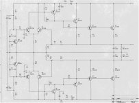
You will want to expand the last picture I posted all the way otherwise it becomes really difficult to read.
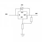
I am also posting a picture of the “known to work” schematic for the Anthony Holton regulator. This one is a little hard to read even when it is expanded all the way. But magnifying it helps.
I am also posting a picture of the “known to work” schematic for the Anthony Holton regulator. This one is a little hard to read even when it is expanded all the way. But magnifying it helps.
Attachments
I wonder how different sound an amp would have if one were to substitute the full regulator circuits suggested with a very large bank of good quality capacitors powered by an oversized discrete transformer. In effect this would serve as a cheaper type of "regulation" as flactuations in voltage would subside if the transformer were able to handle the current drawn being say at a maximum of 20-30% of its power rating.
As Jacco suggested, a small separate PSU for the driver stage would assist against any voltage drop dissipated by the front stages. Moreover the front stage could easilybe regulated with a very simple low current circuit for superior results.
The net effect would be to have full regulation for the driver stage and excellent "pseudo-regulation" of the unregulated PSU for the output stage without needing to power the amplifier by another regulation "amplifier" with the added disadvantages of heatsinking, cost and labor.
If you look at the top US amplifiers in the +250 watt range from the last 20-25 years heavy armor powersupplies were common.
I doubt that Mr Marshall designed his amplifier in the 80s to drive an Apogee or an Infinity IRS.
US amplifiers traded with BIG Holden&Fisher toroids and very large Sprague and Mallory capacitors.
In Europe amp builders went for relatively small transformers and large numbers of small caps.
In Japan the philosophy was to build amplifiers the size of the japanese, small.
No room for big powersupplies,but electronic gadgets.
In my view, a large part of the dominance of US amplifiers was due to stable power, big powersupplies.
An amplifier like the ML23 is in the Super Leach range.
The toroid transformers used in the 23 are 1200VA types.
I believe the capacitors used for the output were double 46.000 uF per channel, connected to the output devices with solid metal bars, an inch wide.
The gain stages had 15.000uF caps, separate windings, and voltage was stabilised for the front end.
The SuperLeach is capable of delivering 300 watts RMS.
With an output stage of minimal 12 devices it has a peak capability of over 2500 watts.
I'd think the amplifier should be capable to deliver next to 900 in 2 ohm, close to 1500 peak.
But that requires a big transformer and big caps, the original powersupply will not hack it.
I quote KiloWattski: Why re-invent the wheel, copycat the artist !
With a bigger powersupply lower ripple comes as a bonus, no need for fancy PSRR mods.
And more stable voltage at lower gains improves sound quality.
The genuine freak skips active regulation anyway, he decorates his livingroom wall with car batteries.
Doesn’t anybody know how to, calculate the values for my circuit?
Villaw,
I believe this quoted post will put an end to your speculation, assuming the results can be believed:
But as I say I’m not taking any chances with the dual taps.
Villaw,
I believe this quoted post will put an end to your speculation, assuming the results can be believed:
In 1983, I took my Leach Monoblocks (Lower Power version) and compared them to another Leach amp that was built dual mono with large toroids >500VA per channel and with similar quality parts.
My regulated amp only sported 300VA hammond standard core with a couple of radio shack 12V@6amp booster transformers.
There was simply no comparison. The unregulated amplifier sounded positively undynamic in comparison. It was very apparent in kickdrums and really low bass transients. In the highs, the regulated amp seem to have more clarity. Yes, we checked the stability of both amps with scopes etc.
To prove that the power supply was the core of the differences, we disconnected his power supply and jumpered my regulator outputs to his amplifier boards. Now his amps sounded similar to mine.
Within a week, owner quickly retrofitted a front end only regulation using lifted discrete regulators ( I think 317/337) and while it had improved a bit, the fully regulated amp was still clearly superior. Needless to say, he had another project that converted his amp to full regulation.
A similar comparison was made with the super leach with similar results. Yes, on paper full regulation of the ouput appears to be unnecessary but close listening proves otherwise. PSRR etc. will say otherwise but the differences exist. Is it worth the extra effort and resources? It depends on what you desire. If you want that extra "kick" for dynamics. Higher wattage may NOT necessarily give that to you. Maybe the lower power version fully regulated might be better from a resource/parts standpoint.
But as I say I’m not taking any chances with the dual taps.
LBHajdu,
"Doesn’t anybody know how to, calculate the values for my circuit? "
It appears not, and what happened to:
"For the front end i mentioned one earlier that can be changed for 90 volts operation. If needed i can deliver ten circuits that do the job. Who knows, maybe Master of the Universe Self made a couple.
For the output stage i can get you one too that does 90 volts in, 75 to 85 volts out, delivering 10 to 20 amps.But tiny question, do you want it ?"
posted earlier.
Even djk says "If you have a design that can be modified to supply those voltages, would it be too much trouble to show how it should be modified to meet that purpose?"
If you can't do it from the instructions provided, maybe...
This is DIYaudio.com last time I checked.
Everyone is eagerly waiting. Seems we must suffer through a history lesson first.
Regarding the "tapped" transformer. I heard of someone using that configuration but adding a "party switch". If the amp was used for party purposes, the regulator was removed/jumpered out and the lower voltage unregulated was used. That way, one need not worry about power dissipation of the regulators in "non critical" listening high continuous power situations.
I've been browsing Linear Tech newer three terminal regs and they appear to be much improved over the older 3 term regulators. Maybe the BOAK regulator needs revisiting by someone more qualified than myself. Keep in mind the boak regulator uses preregulation so that under heavy loads all the pass transistors might see is 5-10 volts.
I've been browsing Linear Tech newer three terminal regs and they appear to be much improved over the older 3 term regulators. Maybe the BOAK regulator needs revisiting by someone more qualified than myself. Keep in mind the boak regulator uses preregulation so that under heavy loads all the pass transistors might see is 5-10 volts.
LBHajdu said:Villaw,
I believe this quoted post will put an end to your speculation, assuming the results can be believed:
[/B]
Well not really because I have read that too and I fully take for granted the writer's tests and comments. My point is strictly limited to the economics and efficiency side of it.
Clarifying, my point is to oversise so much the transformer and have so much rail total capacity as to have an almost constant voltage source. The argument being that it would be easier and less costly to pack up say 100000uf per rail and use a 2kva transformer than use the circuits suggested. This is just a layman's opinion on the subject based on empirical evidence.
Furthermore if one were to choose the smaller leach amp with full regulation then that is another story since for smaller currents regulation is not that much of a hassle.
I am also a keen propounder of the theory of avoiding the reinvention of the wheel as it is very inefficient especially in this area where the larger companies have spent so much R & D on the subject. Even if we argue for the next 20 years to come our finding would still lag behind the research made by the Mark Levinsons and krells of this world. Therefore why not find out what a really successful, in terms of tests etc, amp of similar size uses and copy that. If the case is that of full regulation then I guess there is no point in arguing about it. A place to start is to examine a recent model such as a Krell FBP-600 or other amp not wishing of course to favor Krell over other brands.
LBHajdu said:I have never seen a schematic where a mje340 drives 4 pairs of output devices, so I assume that you need an MJE15032 as a buffer
Did you calculate the gain you need for driving the 21194/21193 ?
The MJL21194/21193 need between 2 and 2.5 volts to open up,
(average is like 2.2 volts i think)
Normal driver current is in the 20 to 50 mA range.
Suppose you choose 25 mA.
Then the emitter value for the ML15032 is :
2.5 V / 25 mA = 100 Ohm.
Once the output devices are open voltage increases on the output, voltage over R23 (?) remains 2.5 volts to keep them open.
Dissipation for R23 is : 2.5*2.5 / 100 = 0.06 watt.
The value for R23 depends on the voltage needed to get the outputs to open, and isnt really dependant on powersupply voltage, as you can see.
With audio amplifier driver stages the current going through the driver influences sound quality, designers try different values to hear ( and measure) what current level is optimal.
Oops, yet another history lesson !
You can do the same for the MJE340(if you think you need it)
jacco vermeulen,
So you agree with me that a buffer is needed in-between the outputs and the MJE340 ?
I’ll plug this into my Multisim2000 software and see if it seems right. I don’t know of I can trust this software, as it is the first time I have used it and I can’t find exactly the transistors I want to use.
If anyone is interested, here is the model as it is now:
Thanks,
Leve
Attachments
In DIY you do some projects then you begin to "push the envelope". DIY is not of necessity for economics sometimes as most commercial products are. There are categories of projects and a regulated supply for an amp is not a "bang for buck" or optimum cost one by any means.
I think the author steered into the "good enough for reasonable cost" camp very quickly and did not discuss what made the Mark Levinson tick
BTW my initials are ML, my amps are ML ( Marshall Leach) and I like ML ( Mark Levinson) equipment but can't justify it. So that tells you of my biases.
I think the author steered into the "good enough for reasonable cost" camp very quickly and did not discuss what made the Mark Levinson tick
BTW my initials are ML, my amps are ML ( Marshall Leach) and I like ML ( Mark Levinson) equipment but can't justify it. So that tells you of my biases.
LBHadju,
The emitter resistors on the output stage can handle nearly 4 amps each before you fry them.
4 in parallel is 15.5 amps, say 16.
The MJL21194 has an Hfe of 25 at 8 amps.
16 amp divided 25 is 640 mA.
The MJE15032 fully open has to push 640 mA in the output devices.
The MJE15032 has a minimum Hfe of 50 on its datasheet.
(not entirely true, for the exact number you need to see the graph)
Means the predriver MJE340 has to deliver 640 / 50 ~ 13 mA.
Then, the MJE340 has an minimum Hfe of 30(sheet, not graph)
So, the MPSA92 has to push 13 / 30 ~ 0.5 mA in the base of the MJE340.
But if you take a look at the sheet for the MPSA92 you'll see that it has an Hfe of minimum 25.
Fully open with only 0.5 mA flowing out of the emitter of the MPSA92 the current coming out of the base is :
0.50 / 25 = 0.02 mA !!!!!!!!
The first MPSA42 connected to R13 has 12 volts on its base, R13 has 11.4 volts behind the emitter of the MPSA42.
Current through R13 is 11.3 / 4.7 k = 2.4 mA.
If there is a current of 0.6 mA flowing through R17 there is a voltagedrop of 0.60 volts on the base of the MPSA92 next to R17.
The difference : 2.4 - 0.60 = 1.80 mA can flow out of the base of the MPSA92.
Before that happens voltage level at the output is high enough to open the second MPSA42, so more current from that will flow into R3 and less from the first MPSA42.
Less current means less through R17, means less voltage drop over R17, less current from the base of the MPSA92.
But anything above 0.02 mA going through it will make the 0.33 ohm resistors go pop !!
Leave the MJE340 out and the required current flowing out of the base of MPSA92 is 30 times 0.02 = 0.6 mA.
An MPSA42 is not the same as a 2SC2240, Hfe for the 2SC2240 is not 30 but 200 minimum, same for the 2SA970
In the original circuit total Hfe from the 2SA970 and the MJE340 is
200 * 30 = 6000.
In yours it is : 25 * 30 * 50 = 37500.
How many amps do you want the output to deliver ?
btw: i would not object to owning a couple of ML2's
Anyone wanting fully regulated ML2's, ask for a thread and design boards. I'll join !!
All original drawings for the ML2 are at www.MarkLev.com
"If needed i can deliver ten circuits that do the job. Who knows, maybe Master of the Universe Self made a couple. For the output stage i can get you one too that does 90 volts in, 75 to 85 volts out, delivering 10 to 20 amps.But tiny question, do you want it ?"
Circuits? Guess not.
Circuits? Guess not.
Mikett said:In DIY you do some projects then you begin to "push the envelope". DIY is not of necessity for economics sometimes as most commercial products are. There are categories of projects and a regulated supply for an amp is not a "bang for buck" or optimum cost one by any means.
I think the author steered into the "good enough for reasonable cost" camp very quickly and did not discuss what made the Mark Levinson tick
BTW my initials are ML, my amps are ML ( Marshall Leach) and I like ML ( Mark Levinson) equipment but can't justify it. So that tells you of my biases.
I believe the author gives a very good account of his empirically based knowledge there but strictly from a subjective perspective. Having noted that however, I take for granted your experiences too to the effect that I shall try your suggestions using Jen's smaller version perhaps at a lower voltage supply and am sure would have tremendous difference.

All in all, what is difficult, and what seems to be the view advocated by Jacco and some of the rest of the members including the TNT author, is that for very high power amps such as the super leach it would be virtually impossible to build a regulated supply to accomodate say 600w at 4 ohms or 900w at 2 ohms without perhaps using 12 power transistors for the PSU alone.

Re: the ML2s, if my experience is anything to go by there are a few points that I have noted.
Using similar parts quality, similar fully regulated power supplies, I have found that I prefer the sound of the standard Leach over that of the Super Leach. Thus a reason why my Super Leach is at rest most of the time now.
Yes, a fast modern power supply does yield better sound quality. I have compared the sound of a prereg Sulzer type to that of the prereg type Jung/Didden type of supply and the differences are immediately obvious. There is simply no comparison. BTW, these PSUs were used with the AD744-811 line preamp. These ICs already sport pretty good PSRR furthermore, the unregulated feed was coming from a 160VA toroid, yet there were differences so PSRR does not tell the whole story.
What if you strapped on a Jung Didden PSU onto the front end of a ML2 and used the standard regulator for the outputs in CLASS A, maybe this amp would be really something. I see the ML2 only uses rails at 24V. Hmmmmmm......
Again for those wanting to build a "statement" amp, I'm not sure the Super Leach is the way to go. I'd tend towards a standard Leach but really put no holds on it. I was twenty years younger, better ears but foolish enough to think I needed a monster amp. Like getting high horsepower autos today.
As for the number of pass transistors and dissipation,it's really not that bad. First you use a large tranformer that does not sag much. That way the delta between the full load and off load voltage is low. Next, my voltage drops were handled in three sections. Preregulation, current sensing, final pass transistor. I calculated that on peaks I wanted 50 amps. At these loads, my prereg pass transistor only saw 5 to 6 volts, and similarly with my final pass. I did not desire a 50amp steady because I never could see a need. The BOAK regulator used a three terminal device in a current split arrangement with the pass transistor. The three terminal device is bolted onto the heatsink and this thermal capacitance allows large current transients to go thru before it shuts down because of heat.
So for music and normal listening, the regulator is fine, not hot at all but on steady current, you have a heat disspation issue and it shuts down as a three terminal device would.
The weakness of this regulator is the speed. There is no doubt about that. However, it is much better than no regulator at all. I'm an engineer and yes, the models say otherwise but I trust my ears and I've been enjoying fully regulated power amps for the last twenty years. I am grateful to TAA publications and DIY fanatics who push the envelope and lead the way. People like J. Didden, Walt Jung, James Boak and of course Marshall Leach and Gary Galo who scouted the territory and reported back. The world is not flat my friends, even though our maps/models tell us so.
Power supply regulation has been a seriously neglected factor because it is commerically impractical except for mega buck equipment and even there, they are copying what amateurs have been doing the past 20+ years.
sorry for long post.
Mikett said:I see the ML2 only uses rails at 24V. Hmmmmmm......
Did you check the output stage bias of the ML2 ?
- Status
- This old topic is closed. If you want to reopen this topic, contact a moderator using the "Report Post" button.
- Home
- Amplifiers
- Power Supplies
- Leach Super Amp Regulated supply