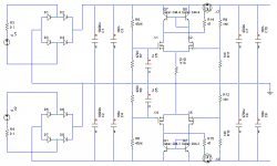
In my continuing quest to do things slightly differently to everyone else, I've come up with some ideas to improve on the capacitance multiplier. I'm developing it to use with the horn subwoofer I'm planning, which being very efficient will want the lowest possible ripple to keep hum down. I've rejected the idea of a normal voltage regulator on the grounds that they are boring.
The improvements were inspired by R.G's thread on amp output protection where he mentioned using P-channel MOSFETs on the positive rail as switches. This made me realize that the same idea could be applied to a capacitance multiplier to lower the dropout voltage (NPN BJTs need a couple of volts; N-channel MOSFETs need even more), further improving what is already one of the main benefits of capacitance multipliers.
The extra drive circuitry necessary to accomplish this also has the benefit of increasing the effective multiplier due to high input impedance. This allows the use of a smaller 'base' capacitor (what was the base capactor anyway - it's not connected to a base now); small enough to make a film cap possible here. Base capacitors can of course still be large for ridiculously low ripple, but it will then take quite a while for the output to ramp up to full potential.
Using low on-resistance MOSFETs, such as IRF5305/IRLZ34N, dropout voltage can be really very low. As low as 0.1V is possible, but more is needed if very high currents are required. This means vanishingly small power disipation, which is nice.
With appropriate component choice this circuit should be able to provide tens of amps with only mV of ripple and very relaxed heatsink requirements. Regulation is not good, but that's because it's not a regulator. It's a bit more complicated than the standard design, but still has a reasonable component count.
Attachments
sometimes boring is better
why not just add voltage references and call your circuit a discrete low drop out series voltage regulator?
in a subwoofer amp you really can't hope for much dynamic headroom from the power supply when the major freq components at the output are much less than the rectified line freq - so a cap multiplier really isn't suited to this app at all
Re: sometimes boring is better
Because...that would be......... BORING!!!!!!1
It always mystifies me how people always want to do roundabout things and totally trash performance for the sake of boredom.
Tim
jcx said:why not just add voltage references and call your circuit a discrete low drop out series voltage regulator?
Because...that would be......... BORING!!!!!!1
It always mystifies me how people always want to do roundabout things and totally trash performance for the sake of boredom.
Tim
Re: Re: sometimes boring is better
Filtering the multiplier's supply doesn't help much since the output is determined by the voltage across X1/X4 gates and ground. Thus ripple rejection is more effected by putting current sources in the tails instead of a resistor, but it still has only a very small effect.
There are improvements to be had by bypassing R9/R13 with large capacitors, and splitting the input filter in two to make it 2nd order, as seen in the ESP project.
Hey, wait a minute! It's hardly totally trashing performance!
P.S. I feel I should point out that the transistors in the top current mirror are upside down.
It's only simulated at the moment since I don't have any spare MOSFETs. Come to think of it, I don't think I've ever used small-signal MOSFETs for anything before.AndrewT said:Hi,
have you tested this circuit yet?
How about an extra CR filter on the supplies to x1 & x4 gates to reduce ripple even further?
Filtering the multiplier's supply doesn't help much since the output is determined by the voltage across X1/X4 gates and ground. Thus ripple rejection is more effected by putting current sources in the tails instead of a resistor, but it still has only a very small effect.
There are improvements to be had by bypassing R9/R13 with large capacitors, and splitting the input filter in two to make it 2nd order, as seen in the ESP project.
Well you're right that there is no advantage for dynamic headroom, but there are multiple other benefits (and disadvantages) for a capacitance multiplier vs. a regulator. For instance:jcx said:why not just add voltage references and call your circuit a discrete low drop out series voltage regulator?
in a subwoofer amp you really can't hope for much dynamic headroom from the power supply when the major freq components at the output are much less than the rectified line freq - so a cap multiplier really isn't suited to this app at all
- Controlled turn-on: it takes a few seconds for the output voltage to ramp up, which reduces current inrush and may help reduce thumps from the amp.
- Reduced power disippation: Allows use of relatively low-power components and small heatsinks, which reduces cost.
- More benign ripple spectrum: Regulators tend to reduce the magnitude of all harmonics evenly, resulting in the output ripple being the same (sawtooth) shape as the input, whereas capacitance multipliers attenuate high frequencies more, resulting in a smooth output ripple.
Yay!Sch3mat1c said:
Because...that would be......... BORING!!!!!!1
It always mystifies me how people always want to do roundabout things and totally trash performance for the sake of boredom.
Tim
Hey, wait a minute! It's hardly totally trashing performance!
P.S. I feel I should point out that the transistors in the top current mirror are upside down.
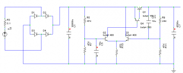
Since it's going to be a while before I can order those MOSFETs, I made a BJT version just for testing, one side of which is shown in the attached schematic.
Resistor values decreased a little to allow for lower input impedance, and capacitors increased to balance. Removed the current mirror because the extra gain makes no difference.
Not much intersting to say about its performance. As the sims predicted, ripple remains very low (just a few mV) when pulling several amps through it, as long as the dropout voltage is high enough. Required dropout is much higher for the BJT version.
Attachments
I made a thread when I built this: http://www.diyaudio.com/forums/power-supplies/53359-finished-capacitance-multiplier.html. I suppose I should have put a link to it in here when I did that. I've been using it for 6 years now, and it has served me well.Any prototypes made with this?
I made a thread when I built this: http://www.diyaudio.com/forums/power-supplies/53359-finished-capacitance-multiplier.html. I suppose I should have put a link to it in here when I did that. I've been using it for 6 years now, and it has served me well.
Mr Evil,
I dont get it.what is a multiplier ?
Why should we call it capacitance multipler ?
I also use somewhat similar circuit in my 12v bench power supply the schematics is a 2n3773 npn transistor biased by a 7805 regulator .the ground pin of 7805 has an 2.2v led and a 5.6 volt zenner doide making the 7805 output 13.1volts.
The good thing is power supply remains hygienically clean of transformer harmonics and impedance and voltage remains dead stable.
Can we call it a capacitance multiplier-How ?
Can it store the charge longer -How ?
It's called a capacitance multiplier because that's a literal description of what it does. In essence, it consists of an RC filter with the voltage across the C used as the input to an amplifier. The behaviour of the resulting circuit is similar to a real capacitor with a size equal to C x the current gain, hence the name "capacitance multiplier".Mr Evil,
I dont get it.what is a multiplier ?
Why should we call it capacitance multipler ?
I also use somewhat similar circuit in my 12v bench power supply the schematics is a 2n3773 npn transistor biased by a 7805 regulator .the ground pin of 7805 has an 2.2v led and a 5.6 volt zenner doide making the 7805 output 13.1volts.
The good thing is power supply remains hygienically clean of transformer harmonics and impedance and voltage remains dead stable.
Can we call it a capacitance multiplier-How ?
Can it store the charge longer -How ?
Yes, normal voltage regulators do exactly the same thing, but with a voltage reference in place of the RC filter. So I suppose using the same logic, a regulator could be called a "voltage reference multiplier".
Capacitance multipliers don't behave exactly like real capacitors. The big difference is that they can't store energy (a bit like how a Gyrator looks like an inductor, but can't store energy).
It's called a capacitance multiplier because that's a literal description of what it does. In essence, it consists of an RC filter with the voltage across the C used as the input to an amplifier. The behaviour of the resulting circuit is similar to a real capacitor with a size equal to C x the current gain, hence the name "capacitance multiplier".
Yes, normal voltage regulators do exactly the same thing, but with a voltage reference in place of the RC filter. So I suppose using the same logic, a regulator could be called a "voltage reference multiplier".
Capacitance multipliers don't behave exactly like real capacitors. The big difference is that they can't store energy (a bit like how a Gyrator looks like an inductor, but can't store energy).
What if we call it a typical current buffer rather the imaginary 'capacitor ' multiplier ?
And my logic says to be a proper capacitor multiplier it needs high enough input voltage headroom e.g Output+5volts.
Ps:I am trying to learn.
Last edited:
Everything needs a proper name so you can talk about it with other people and have them know what you are referring to. I'm not sure if that's the answer you're looking for.What if we call it a typical current buffer rather the imaginary 'capacitor ' multiplier ?
And my logic says to be a proper capacitor multiplier it needs high enough input voltage headroom e.g Output+5volts.
Ps:I am trying to learn.
Regarding headroom: a capacitance multiplier has no inherent limit on input voltage. If the input voltage increases, the output voltage will increase proportionally (minus the small voltage lost across the pass transistor). Ripple rejection will be maintained regardless of changes in input voltage. This is one of the features that make it better than a voltage regulator in certain cases.
It doesn't work like that the other way though, i.e. you can't "charge" it by injecting a current into the output, but that's just because this circuit doesn't need to do that; you could design a circuit that behaved more symmetrically.
I am eagerly looking for a multiplier to use in my car.One I have is capacitor bank 10000x20=200000Mfd and it is bulky which is still much less.Everything needs a proper name so you can talk about it with other people and have them know what you are referring to. I'm not sure if that's the answer you're looking for.
Regarding headroom: a capacitance multiplier has no inherent limit on input voltage. If the input voltage increases, the output voltage will increase proportionally (minus the small voltage lost across the pass transistor). Ripple rejection will be maintained regardless of changes in input voltage. This is one of the features that make it better than a voltage regulator in certain cases.
It doesn't work like that the other way though, i.e. you can't "charge" it by injecting a current into the output, but that's just because this circuit doesn't need to do that; you could design a circuit that behaved more symmetrically.
I wish I could get away with semiconductors.
So I have been playing around with a simplified version of the MrEvil circuit, similar in structure to PMI's alteration of the design but even more stripped down and using BJTs for the differential amplifier. Today I got the idea that the capacitance multiplier pass transistors could be an opportunity to incorporate DC offset protection by forcing them into cutoff and latching them that way. Anyone else given this any thought? I'll post up something later when I'm in front of my computer.
Jason Kuetemann
---------------------
When the student is ready the master appears.
Jason Kuetemann
---------------------
When the student is ready the master appears.
I think that adding a control input is a good idea. It would not even have to latch, in my opinion.So I have been playing around with a simplified version of the MrEvil circuit, similar in structure to PMI's alteration of the design but even more stripped down and using BJTs for the differential amplifier. Today I got the idea that the capacitance multiplier pass transistors could be an opportunity to incorporate DC offset protection by forcing them into cutoff and latching them that way. Anyone else given this any thought? I'll post up something later when I'm in front of my computer.
...
Even something as simple as a remote turn on/off could be useful. All of the extra logic and overhead circuitry could be on a separate board with the fault detection circuitry, and not burden the power supply for those who don't want to use it... (?)
So I have been playing around with a simplified version of the MrEvil circuit, similar in structure to PMI's alteration of the design but even more stripped down and using BJTs for the differential amplifier. Today I got the idea that the capacitance multiplier pass transistors could be an opportunity to incorporate DC offset protection by forcing them into cutoff and latching them that way. Anyone else given this any thought? I'll post up something later when I'm in front of my computer.
Jason Kuetemann
---------------------
When the student is ready the master appears.
Some body tried a similar idea in JLH10w thread, with the relay contacts in the pass transistor base line.
Eagerly waiting for your development.
Member
Joined 2009
Paid Member
The thing is, the 'last capacitor' in the power supply is where your Class AB signal currents flow so you want a good sized capacitor - it's not about ripple reduction but having a good return path for AC currents where some people have claimed that a regulated supply or cap multiplier doesn't sound right without large caps after it. And these caps may store enough energy to destroy a speaker voicoil so you need your dc protect in a different place than where you put your capacitance multiplier.
Done, and tested, and in use with a couple different amps, w. 4700uF output caps. See related thread:The thing is, the 'last capacitor' in the power supply is where your Class AB signal currents flow so you want a good sized capacitor ...
http://www.diyaudio.com/forums/powe...hed-capacitance-multiplier-2.html#post3557054
The main reservoir cap should be selected with an eye toward the intended voltage drop at the pass transistor.
The output cap should be chosen according to the needs on the intended amplifier.
(I believe the original design was intended for a subwoofer supply.)
- Home
- Amplifiers
- Power Supplies
- Improving the capacitance multiplier