Hi,
I have recently acquired some big transformers (2 at about 50V, 50A) as well as big heatsinks and many smoothing capacitors. I would like to build a variable voltage power supply, for +/- 0 to around 65VDC at 10-20A.
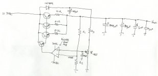
I have searched this forum and the web but have found nothing as of yet, so I have attempted to design my own (attached). The attached file is only for the positive side - I will duplicate this on the negative side, except have another error amp instead of the variable resistor to make sure that the magnitudes of each rail are the same.
The op-amp in it will be a discrete one made out of high voltage transistors etc, and should (hopefully) function as an error amp to minimise error between the two inputs - thus the variable voltage. The series NPN pass transistors are whatever is suitable (current, voltage specifications, etc - no problems there for me) and the NPN transistor driving the base will be probably a MJE340 or similar (whatever). The resistors without values I can easily determine later.
I will also put a regulator in front of the adjustable input - I just thought of that now, so there should be no problems getting that stable (no need for the diode and 1000uF cap then).
Will this work? Any frequency compensation capacitors needed anywhere?
Thanks in advance for any help,
Chris.
I have recently acquired some big transformers (2 at about 50V, 50A) as well as big heatsinks and many smoothing capacitors. I would like to build a variable voltage power supply, for +/- 0 to around 65VDC at 10-20A.
I have searched this forum and the web but have found nothing as of yet, so I have attempted to design my own (attached). The attached file is only for the positive side - I will duplicate this on the negative side, except have another error amp instead of the variable resistor to make sure that the magnitudes of each rail are the same.
The op-amp in it will be a discrete one made out of high voltage transistors etc, and should (hopefully) function as an error amp to minimise error between the two inputs - thus the variable voltage. The series NPN pass transistors are whatever is suitable (current, voltage specifications, etc - no problems there for me) and the NPN transistor driving the base will be probably a MJE340 or similar (whatever). The resistors without values I can easily determine later.
I will also put a regulator in front of the adjustable input - I just thought of that now, so there should be no problems getting that stable (no need for the diode and 1000uF cap then).
Will this work? Any frequency compensation capacitors needed anywhere?
Thanks in advance for any help,
Chris.
Attachments
Yipes! That circuit is a controlled voltage dropper, not a regulator. To use the word "regulator" is a total disgrace to the word's honor!
Yipes! x 2 = 65V dropped at 20A? are you [*]!?
[*]Insert unintelligent adjective here. Unfortunately this board forces me to use this parenthetical description, rather than outright saying it, something which would capture my passion in typing a bit better.
Tim
Yipes! x 2 = 65V dropped at 20A? are you [*]!?
[*]Insert unintelligent adjective here. Unfortunately this board forces me to use this parenthetical description, rather than outright saying it, something which would capture my passion in typing a bit better.
Tim
I don't understand what the big problem is:
I said that the power supply to the variable resistor would be regulated (LM317 I guess). This provides a nice stable voltage - the error amp then compares this to the output of the amp (via suitable scaling resistors) and adjusts its output to match - this should be a nice stable output too then. Please correct me if I'm wrong.
I said that the power supply to the variable resistor would be regulated (LM317 I guess). This provides a nice stable voltage - the error amp then compares this to the output of the amp (via suitable scaling resistors) and adjusts its output to match - this should be a nice stable output too then. Please correct me if I'm wrong.
Well, conceptual it will work (if you turn that top diode around). But to get good regulation to 20A you need some more currect loop gain, but maybe your discrete opamp can handle a big drive current.
Couple of things: if you take the trouble to use a separate +/- 15V, 200mA or so, floating supply for the opamp (with that supply referenced to the output voltage) the whole reg can float up and down and you can use standard opamps - much simpler than building a +/- 75 V discrete opamp - you've no idea what you're getting in to here!
The prereg thing you mention - I don't see what that brings you in terms of output performance.
Lastly, if you regulate the output down to say 5V and draw say 15 Amps, that reg needs to sweat out over a kilowatt. Do you realise what that means in terms of heatsinks and number of series transistors?
Jan Didden
Hi Jan,
Thanks for your reply. Just note that the diode is not connected to the output of the power supply at all. Its purpose was to provide a stable supply to the variable resistor, which is what the output voltage would be referenced to. This way no transients on the line will affect the voltage on the input to the diff amp. However, the actual steady state voltage will vary with output current, so this affects the adjustment voltage reference - hence why I said I'd put a regulator there instead of the diode/capacitor combination.
I like your idead of using a floating voltage op amp configuration: I could reference the ground supply of the op amp to Vout, and have that as the -ve input, with the +ve input derived from my LM317 based regulator - that should work hopefully?
Also, I do understand the implications of the power required to be dissipated.... I plan on using this power supply to test new amps that I may build, as well as general stuff. Obviously I am not going to be drawing 15A at 5V very often! (though if I really wanted, I do have some really big heat sinks that would be big enough). I just thought that since I have high current available from the tranfos (50A!), I may as well make use of some of it.
One thing is I don't want this power supply to turn into a big oscillator - will I need frequency compensation stuff at all, do you know?
Thanks,
Chris.
real said:Hi Jan, Thanks for your reply. Just note that the diode is not connected to the output of the power supply at all. Its purpose was to provide a stable supply to the variable resistor, which is what the output voltage would be referenced to. [snip]
I see, yes, that's OK, didn't catch that. Of course, you could take that ref from the output, even better. No need for a prereg.
real said:[snip].
I like your idead of using a floating voltage op amp configuration: I could reference the ground supply of the op amp to Vout, and have that as the -ve input, with the +ve input derived from my LM317 based regulator - that should work hopefully?[snip]
Depends on the opamp used. The opamp output will be just a few volts above the output voltage. If this is an opamp wth rail-to-rail output swing, OK. Otherwise you need bipolar +/-15V re: output.
real said:[snip].[snip]Also, I do understand the implications of the power required to be dissipated.... I plan on using this power supply to test new amps that I may build, as well as general stuff. Obviously I am not going to be drawing 15A at 5V very often! (though if I really wanted, I do have some really big heat sinks that would be big enough). I just thought that since I have high current available from the tranfos (50A!), I may as well make use of some of it.[snip]
You probably want some current limiting. Like sampling the voltage across those .1 ohms resistors and shunting the drive to the driver if you get to the set limit.
real said:[snip]One thing is I don't want this power supply to turn into a big oscillator - will I need frequency compensation stuff at all, do you know? Thanks, Chris.
It WILL oscillate, the first time you try, don't worry. Unless you are REALLY good at that stuff. But as a minimum, make sure you have the wiring done well, star ground, no heavy current wires close to the reg circuit, that sort of thing. This is a major project.
Jan Didden
- Status
- This old topic is closed. If you want to reopen this topic, contact a moderator using the "Report Post" button.
- Home
- Amplifiers
- Power Supplies
- High Current Variable Voltage Power Supply