Hey guys, anyone got some diagrams for creating any sort of dc/dc converter using parts from a computer PSU? Ive got quite a bit of old ones lying around, ones that use TL494 etc.
Id like to use parts from them to create a converter that accepts 12v from like a car, and then converts it to around 80v
Thanks in advance
~Pentarino
Id like to use parts from them to create a converter that accepts 12v from like a car, and then converts it to around 80v
Thanks in advance
~Pentarino
TL494-based DC-DC
Pentium-
Yes, you can. Look as any car amplifier with a DC-DC converter- they almost always use the '494. Some, like Alpine, might even have tech manuals available, complete with schematics in them.
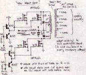
If you really want to stay with the form-factor of the AT- or ATX-box, I seem to remember a website where the guy kept the secondary (output) section intact, but changed the input side from the hi-voltage half-bridge configuration to a low-voltage (probably 12V) center-tap push-pull topology. He kept the driver transformer, but with a little re-working of the circuit layout. The 400V bi-polars were swapped out for some 55-60V N-Channel MOSFETs of low Rds(on) rating. If I find it, I will post the web address on this thread.
His article accompanying the photos seemed to indicate good success with the project. So now, he can use his desk-top CPU on 12VDC instead of the regular 120VAC. Probably a good thing in the event of a power outage.
Since you're probably wanting to make a (+/-) supply, you will need to do something different. For usable parts on a typical AT or ATX PSU, assuming it is a half-bridge and not a flyback, you can use the transformer (though some rewinding will be necessary), the BIG output inductor, some of the little individual output inductors, the output rectifiers (they're the high-speed types), and, of course, the TL494 itself. But you're in for some new transistors, and a driver ckt, as the 494 will not directly drive MOSFETs. The electrolytic caps might be used, although you might want to use some better caps, like Panasonic, or others.
The electrolytics in the output section are rated for only 10- or 16VDC, and might not have high enough voltage rating for your application. In this case, you will definitely need some new caps, Low ESR, rated for high-frequency applications, and you might want to look at a really good brand, like Panasonic or Sprague, or some other high-quality brand.
Anyway, I am rambling, but if I come across that conversion project, I will post the link for it on this thread.
Steve
Pentium-
Yes, you can. Look as any car amplifier with a DC-DC converter- they almost always use the '494. Some, like Alpine, might even have tech manuals available, complete with schematics in them.
If you really want to stay with the form-factor of the AT- or ATX-box, I seem to remember a website where the guy kept the secondary (output) section intact, but changed the input side from the hi-voltage half-bridge configuration to a low-voltage (probably 12V) center-tap push-pull topology. He kept the driver transformer, but with a little re-working of the circuit layout. The 400V bi-polars were swapped out for some 55-60V N-Channel MOSFETs of low Rds(on) rating. If I find it, I will post the web address on this thread.
His article accompanying the photos seemed to indicate good success with the project. So now, he can use his desk-top CPU on 12VDC instead of the regular 120VAC. Probably a good thing in the event of a power outage.
Since you're probably wanting to make a (+/-) supply, you will need to do something different. For usable parts on a typical AT or ATX PSU, assuming it is a half-bridge and not a flyback, you can use the transformer (though some rewinding will be necessary), the BIG
output inductor, some of the little individual output inductors, the output rectifiers (they're the high-speed types), and, of course, the TL494 itself. But you're in for some new transistors, and a driver ckt, as the 494 will not directly drive MOSFETs. The electrolytic caps might be used, although you might want to use some better caps, like Panasonic, or others.The electrolytics in the output section are rated for only 10- or 16VDC, and might not have high enough voltage rating for your application. In this case, you will definitely need some new caps, Low ESR, rated for high-frequency applications, and you might want to look at a really good brand, like Panasonic or Sprague, or some other high-quality brand.
Anyway, I am rambling,
but if I come across that conversion project, I will post the link for it on this thread. Steve

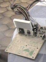
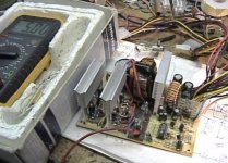
DC-DC ATX PSU Pics
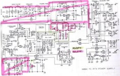
....and the last one. tThe schematic os for a 200W unit, although it is adaptable for almost any ATX PSU. NOTE: These are NOT pics of my work- I pulled them off the web almost a year ago. Just wanted to post them here to answer your original question.
Hope these help, and I'm sorry it took soooooooooooo long!
Steve
Attachments
- Status
- This old topic is closed. If you want to reopen this topic, contact a moderator using the "Report Post" button.
- Home
- Amplifiers
- Power Supplies
- DC/DC converter using parts from PC PSU