The schematic above is conceptual. Some math is needed to work out actual values. The one's I used are sort of close but the 10 Ohm or the 470uF needs work.
In the real world probably one of those programable zeners (actually a shunt regulator with a built in reference) on the pass element base could be made to work. The gain of this device would eliminate the 470uF and the resistor to ground. The actual value of the 10 Ohm depends on voltage, current and beta of the pass element. Design for about 1/2 of specified minimum gain to leave some headroom and to make it work at frequencies higher than DC.
I assumed from your first drawing you knew how to do much of this kind of thing.
I personally wouldn't bother with regulation to the output stage, it's unlikely to make any difference. Most high end amps don't have it. Yes a few of them do, but they don't perform any better than the ones that don't.
Just regulate the voltage gain stages. If you go to http://www.bryston.ca.schemprod, they have their schematics, and you can see how they do it.
Just regulate the voltage gain stages. If you go to http://www.bryston.ca.schemprod, they have their schematics, and you can see how they do it.
You will not kick yourself if you have an excessively quiet power supply. You may say bad words if you have to tear it all up once constructed to add filtering. Overkill will only hurt the sound of the amplifier to some people. Trial and error will be called for if you feel that to be the case with too quiet of a supply.
> I don't fully agree with that...
It does not matter if we agree; reality is the only truth.
I believe the truth is that you are working against a fallacy. Reality may prove me wrong, but I'm pretty sure. If so, all this talk of SOA and tranny-spikes, which are of course just solvable engineering problems, misses the mark completely.
> With the capacitors on the AC line, I was getting about a 2.5 volt ripple at 84VDC, so that wasn't really bad.
It's 3% ripple, a perfectly reasonable value for the first stage.
> The signal coming out of the transformer would have been squarish, but that's all the better as rectified full wave that would have produced a near perfect DC on it's own, even without the 4 10,000uf caps
Right, almost. And for the moment, for analysis, ignore the added capacitors. The square wave avoids the dip at zero-crossing (actually, from one peak to the other peak) that we have with a sine. With a perfect square and a perfect rectifier, the output is perfect DC.
But the square is not perfect. It has 3% of 120Hz ripple! Assuming perfect transformation and no further capacitance, the "DC" will have 3% ripple.
Still assuming perfect transformation and rectification, your 20,000uFd of amp-rail capacitance simply reflects back onto the line-caps.
Hmmmm... if V*uFd/$ is a constant, there is some advantage in filtering at higher voltage and lower current. 100V and 1A needs 1,000uFd for 1% ripple. 200V and 0.5A needs 250uFd for 1% ripple. Since V*uFd/$ of suitable commercial capacitors is approximately constant, there is some advantage in doing your filtering at higher voltage, if you can transform cheaply.
You won't have perfect transformation. In one sense, that is good: the transformer impedance makes this a 2-stage filter. But a resistor could do that cheaper, and a choke could do it better.
When you need DC cleaner than around 2% ripple, you should consider a multi-stage filter. That used to be common: when caps cost a lot (in 1938) all radios had chokes. The advent of incredibly cheap big-caps changed that: more aluminum is cheaper than iron/copper. But consider a design where you are given just two caps. And say one cap gives 3% ripple. Adding the second cap in simple parallel gives 1.5% ripple. Building a C-R-C filter with 2% loss in the R will give about 14dB reduction on the 3% ripple, or around 0.7% ripple. Stuffing dead resistance in the power leads goes against the grain. It "clearly reduces output". But hi-fi amp clean output is limited by the dip of the ripple. Taking a little loss to get less-deep dips doesn't hurt much. And in Class AB speech/music, it hurts very little: loss at low output is negligible and peaks will reproduce well, only test-tone power is reduced.
If you want a radical clean-AC/DC supply: put a 4" pulley on a 3600RPM AC motor and belt it to a car alternator. A car alternator makes about 1V/100RPM: above engine-idle, a regulator kills the field coil to hold the output down to 13V. Booger that regulator, you can get 60-70V at large Amps. And at somewhat higher frequency. AND the output is 6-phase power: even without a cap, the output never drops to zero! IIRC it is around 15% ripple unfiltered, and a whole lot easier to clean-up than single-phase. However noise (acoustic and brush-hash) may be a problem.
> if I'm using a design where I know the power supply rejection ratio, how can I use that to determine how much of an affect a voltage ripple will have (assuming an unregulated supply)?
100V supply. 5% ripple. There is 5V ripple on the rail. Say amp has 40dB or 100:1 ripple rejection. Ripple on the output is 5V/100 or 0.050V. 0.05V in 8Ω is 35dB below 1 Watt. Assuming 90dBSPL/Watt speakers, ripple is 90-35= 55dB SPL of buzz a yard in front of the speakers (and about 52dB SPL everywhere in an average residential room). That's a lot of buzz. (Real-world PSRR is never as simple as this computation, but it will tell you if you are in trouble.)
We can usually design for less than 5% ripple. And a secret advantage of Class AB operation is that supply current and ripple are low at low output, when buzz is most audible. Many amps buzz when pushed up near clipping, and some show it on test, but it is often negligible to the ear. Class A pulls full power (and ripple) all the time, and more supply power than a Class AB amp working to max.
And 40dB PSRR is pretty crummy for a power amp. Low-level stages sometimes get away with 6dB PSRR, but their power demand is so low we can use "wasteful" power filtering. That's awful expensive in a POWER stage. Fortunately a BJT's Collector, which is "an input", is about 1,000 times less sensitive than its Base. So if you can get clean power to the driver, and hold the output devices' Bases at signal voltage without ripple, the output stage has nearly 60dB PSRR without any special care. Combine that with Class AB operation (low ripple at idle) and some NFB, any buzz on the output is probably due to layout, not power supply. (And I've been guilty of throwing time and money into a power supply when the buzz was elsewhere.)
> I have a limited budget,
An amp that drinks 15 Amps seems "big" to me. Can't fight the laws of physics or factories. Big amps cost big bucks.
hermanv said:
Driving transformers with square waves can be made to work fine. Its done all the time
Hi !
Yes, SMPS does this, but with very small transformers and high freqs.
But this is not too easy, if switching is not done carefully, you get
some loud bangs. And the calculations with number of windings from
primary to secondary are only valid for sinus.
I don't know how exactly these issues are adressed in an SMPS,
maybe EVA can say something ?
For the case of switching, SOA is not really relevant, as the transistor
only sees on/off, you have only max voltage with 0 amperes, and
max amperes with nearly 0volts vce. Also heating is very small.
Only the transient during switching needs to be observed, and the
energy fighting back from the inductive load is critical.
Mike
rjon17469 :
You are effectively trying to design an offline SMPS and your circuit concept is right except for inadequate components and some mistakes
When rectifiying mains AC you can't use earth as a reference, no current at all should flow between mains and earth [actually a few mA are allowed and sometimes required for proper EMI filtering]. Also note that 120Vrms AC rectification produces about 170V DC [1.4142*120V]
Direct mains rectification has some advantages, one of them is that high voltage electrolytic capacitors tend to store more energy in less space at less cost. This produces less ripple and uses less space for the same price. You can compare .5*C*V^2 / volume [joules/cm^3] for different capacitors
Transformers may be driven with any waveform, even with DC if the core is gapped. For power conversion applications, the best efficiency happens when transformers are driven from square waves. Driving transformers with sine waves produces inferior efficiency and requires an oversized transformer. A transformer rated at 500VA for 120Vrms AC sinewave will be rated at 1000VA for +-120V of squarewave amplitude [240Vpp] [volts*turns/seconds product is the same in both cases so the same flux is generated in the core]
This happens because square waves transfer the maximum power during the entire cycle while sine waves only transfer the maximum power during 30% of the cycle. Doing the math : The peak current for a given power output is 1.4142 times higher in a sine wave and the copper losses are twice as high as for a square wave, given the same transformer
Transformer efficiency is particularly improved with square waves when the secondary side is rectified, since a peak-rectified sine wave does not transfer power at all for 70% of the time and has to transfer 3 times the output average power during only 30% of the time, causing 3 times higher copper losses and 9 times higher voltage drop in comparison with a resistive load
So driving transformers with square waves requires less copper saving space and reducng weight...
But the most smart feature of driving transformers with a squarewave generated from a switched DC source is that you can change the frequency and the duty cycle
For a given transformer core, the number of primary turns required to avoid saturation is proportional to the maximum allowed voltage and inversely proportional to the minimum allowed frequency. Also, for a given number of turns, the mass of iron or ferrite required by the transformer core is proportional to the maximum allowed voltage and inversely proportional to the minimum allowed frequency
So theoretically : A transformer operating at 50Hz requires 100 times more turns than one operating at 5Khz. Or : A transformer operating at 50Hz requires 100 times more core mass than one operating at 5Khz. Or : A transformer operating at 50Hz requires 10 times more turns and 10 times more core mass that one operating at 5Khz. Etc...
In practice, there is some dissipation in the core that increases with frequency and limits the maximum operating frequency for that core material
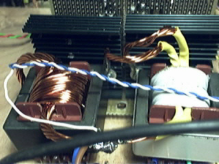
In fact, one of these E42 ferrite transformers, measuring 42 x 42 x 40mm, weighting less than 500g and costing less than 5 euro [raw core and former without windings] ...
Is happily capable of transferring 1KW of continuous power when used at 35Khz, a pretty small switching frequency for today's standards. At 100Khz [maximum recomended operating frequency for that material] it can transfer more than 2KW
But controlled square waves have another advantage : Output regulation. If you place a LC lowpass filter at the output of the transformer just after the diodes, then the output voltage will be the square wave amplitude multiplied by the duty cycle. Also the LC lowpass filter effectively filters the square wave and attenuates the switching transients down to a few milivolts
Regulation allows to convert a high voltage with lots of ripple into a lower voltage with milivolts ripple
But switching high voltages optimally, designing optimum transformers and LC filters, and making all them operate inside a stable closed regulation loop is somewhat harder than making an audio amplifier work
If you want to go on with this project, you should start reading and learning about SMPS and experimenting with low voltages, and also get an oscilloscope if you still haven't one
[Disclaimer : Never try to build anything that switches high voltages and/or currents before completing and optimizig some projects using lower voltages and currents. Allways test the high-voltage circuits with lower voltages first. Never use mains as a direct high voltage supply for experimentation, use 1:1 isolation transformers. Use a light bulb in series with the power supply when first testing with high voltages. Follow proper mains isolation rules when building transformers and tracing PCBs. Do everything at your own risk. Etc...]
You are effectively trying to design an offline SMPS and your circuit concept is right except for inadequate components and some mistakes
When rectifiying mains AC you can't use earth as a reference, no current at all should flow between mains and earth [actually a few mA are allowed and sometimes required for proper EMI filtering]. Also note that 120Vrms AC rectification produces about 170V DC [1.4142*120V]
Direct mains rectification has some advantages, one of them is that high voltage electrolytic capacitors tend to store more energy in less space at less cost. This produces less ripple and uses less space for the same price. You can compare .5*C*V^2 / volume [joules/cm^3] for different capacitors
Transformers may be driven with any waveform, even with DC if the core is gapped. For power conversion applications, the best efficiency happens when transformers are driven from square waves. Driving transformers with sine waves produces inferior efficiency and requires an oversized transformer. A transformer rated at 500VA for 120Vrms AC sinewave will be rated at 1000VA for +-120V of squarewave amplitude [240Vpp] [volts*turns/seconds product is the same in both cases so the same flux is generated in the core]
This happens because square waves transfer the maximum power during the entire cycle while sine waves only transfer the maximum power during 30% of the cycle. Doing the math : The peak current for a given power output is 1.4142 times higher in a sine wave and the copper losses are twice as high as for a square wave, given the same transformer
Transformer efficiency is particularly improved with square waves when the secondary side is rectified, since a peak-rectified sine wave does not transfer power at all for 70% of the time and has to transfer 3 times the output average power during only 30% of the time, causing 3 times higher copper losses and 9 times higher voltage drop in comparison with a resistive load
So driving transformers with square waves requires less copper saving space and reducng weight...
But the most smart feature of driving transformers with a squarewave generated from a switched DC source is that you can change the frequency and the duty cycle
For a given transformer core, the number of primary turns required to avoid saturation is proportional to the maximum allowed voltage and inversely proportional to the minimum allowed frequency. Also, for a given number of turns, the mass of iron or ferrite required by the transformer core is proportional to the maximum allowed voltage and inversely proportional to the minimum allowed frequency
So theoretically : A transformer operating at 50Hz requires 100 times more turns than one operating at 5Khz. Or : A transformer operating at 50Hz requires 100 times more core mass than one operating at 5Khz. Or : A transformer operating at 50Hz requires 10 times more turns and 10 times more core mass that one operating at 5Khz. Etc...
In practice, there is some dissipation in the core that increases with frequency and limits the maximum operating frequency for that core material
In fact, one of these E42 ferrite transformers, measuring 42 x 42 x 40mm, weighting less than 500g and costing less than 5 euro [raw core and former without windings] ...
An externally hosted image should be here but it was not working when we last tested it.
Is happily capable of transferring 1KW of continuous power when used at 35Khz, a pretty small switching frequency for today's standards. At 100Khz [maximum recomended operating frequency for that material] it can transfer more than 2KW
But controlled square waves have another advantage : Output regulation. If you place a LC lowpass filter at the output of the transformer just after the diodes, then the output voltage will be the square wave amplitude multiplied by the duty cycle. Also the LC lowpass filter effectively filters the square wave and attenuates the switching transients down to a few milivolts
Regulation allows to convert a high voltage with lots of ripple into a lower voltage with milivolts ripple
But switching high voltages optimally, designing optimum transformers and LC filters, and making all them operate inside a stable closed regulation loop is somewhat harder than making an audio amplifier work
If you want to go on with this project, you should start reading and learning about SMPS and experimenting with low voltages, and also get an oscilloscope if you still haven't one
[Disclaimer : Never try to build anything that switches high voltages and/or currents before completing and optimizig some projects using lower voltages and currents. Allways test the high-voltage circuits with lower voltages first. Never use mains as a direct high voltage supply for experimentation, use 1:1 isolation transformers. Use a light bulb in series with the power supply when first testing with high voltages. Follow proper mains isolation rules when building transformers and tracing PCBs. Do everything at your own risk. Etc...]
Hi eva !
Phew, that's a lot of knowhow in one single post...
What i don't understand, i remember that a transformer outputs
the reverseintegral (just don't know the english word) of the input,
means sin -> cos. But this would be infinite for squarewave ?
A triangle should output a square. Am i wrong ?
Mike
Phew, that's a lot of knowhow in one single post...
What i don't understand, i remember that a transformer outputs
the reverseintegral (just don't know the english word) of the input,
means sin -> cos. But this would be infinite for squarewave ?
A triangle should output a square. Am i wrong ?
Mike
if you are going to use Bipolar transistors you have to seriously consider using a "current mode" controller chip instead of an LM555 multivibrator -- unless the transformer is perfect etc., etc. the transformer could go into saturation and pop the transistors (semiconductors as fuses!). A current mode controller costs only a few cents more than a multivibrator, and controls the device on a pulse by pulse basis.
But firstly, there so many application notes on this type of design from Texas Instruments, National Semiconductor, On-Semi that before you put soldering iron to PCB trace it would serve you well to peruse the manufacture data-sheets and apnonte.
Lastly, off line switchers -- there is a good reason that there is a steel case around them and it isn't just EMI considerations. In addition to what EVA said, I would add that you put the device in a cage (used ATX supply) in case some capacitor gets unhappy and decides to blow its lid!
A ideal transformer outputs exactly the inputsignal scaled by the turns ratio, the current is also inversely scaled
If whe have an ideal transformer with two windings, one of 20 turns and one of 10 turns then :
The instantaneous voltage across the 20 turn winding is allways twice than in the 10 turn one
The instantaneous current through the 20 turn winding is allways half than in the 10 turn one
Real transformes also suffer from :
- Leakage inductance : Adding an inductor in series with each winding of the ideal transformer models this quite well
- Magnetizing inductance : It's modelled quite well adding a inductor with a certain saturation current in paralell to one of the windings of an ideal transformer. The voltage applied to this inductance must be flipped periodically to avoid saturation. In gapped transformers this inductance has a high saturation current while in ungapped transformers it saturates when a few mA are reached, altough this takes some time since its value is usually quite high
Infinite current with ideal square waves only happens in ideal capacitors
Voltage squarewaves produce triangle current waves in inductors
Eva said:
Voltage squarewaves produce triangle current waves in inductors
Ah, that was my missing point !
This means, after rectifying the output, it's "pure" DC ?
(I should send some bomb to my physic-teacher, i should have known
that ALL information from him is somehow wrong...)
Mike
No, I'ts a square wave filtered by LC filters made with non-ideal components
After a good LCLC filter the square wave may appear as a 1mv p-p triangle wave on top of the DC component...
Anyway, filtering ripple is very easy but preventing diodes and transistors from ringing at 15, 25 or 40Mhz is not so easy
After a good LCLC filter the square wave may appear as a 1mv p-p triangle wave on top of the DC component...
Anyway, filtering ripple is very easy but preventing diodes and transistors from ringing at 15, 25 or 40Mhz is not so easy
Man, I'm think I got enough stuff here to write a book!
So, I am able to do this, however it will take some low-level experimenting first with some design modifications.
Well, I'm definitely not going to use this as my power supply in my first design, but definitely later on I'll give it a shot (in a low voltage/low current design).
So, it is possible to use this design though say with 30kHz switching? The reason I chose 200Hz was I didn't know if I could get good power output switching really fast.
Thanks to all!
Reece
Because the people who designed the power supply for the computer sitting next to me knew exactly what they were doing. ;-)
It's definitely something I plan to do, and I'll probably even make my current amp so that I can pull out the current power supply and put a new one in. But for the time being I'll stick with the typical.
Reece
It's definitely something I plan to do, and I'll probably even make my current amp so that I can pull out the current power supply and put a new one in. But for the time being I'll stick with the typical.
Reece
> What i don't understand, i remember that a transformer outputs the reverseintegral (just don't know the english word)...
Differential, differentiation.
> of the input, means sin -> cos. But this would be infinite for squarewave?
That happens when you study the current in the transformer. That is commonly done in engineering courses: don't shoot the professor. In many real-world cases though, we apply a constant-voltage AC source and ignore the current.
Transformers are not that complicated. They also give no ripple reduction. As Eva and I have said, Reece can gain some economic advantage by doing ripple filtering at higher voltage, if he can use power at that voltage or transform it cheaper than simply adding more low-volt caps.
I do doubt his original plan will hold smoke, but getting the smoke to stay inside is a "simple" engineering chore (probably involving more/bigger parts).
But anything along these lines is not going to reduce ripple except the slight economic advantage from doing filtering at high voltage.
A full SMPS can adjust on-periods to regulate the output, but a 200Hz switching frequency isn't going to straighten-out 120Hz ripple. 35KHz will, but commodity transformers will just choke, and commodity transistors may not be fast enough, or need very stern drivers. It is a design specialty. And while some excellent switch-mode audio exists, keeping a 35KHz bee-buzz boxed up and out of your audio paths is an added complication.
For a DIYer, swtiching supplies aren't really practical. It would be nice if a company came out with supplies just for specific popular DIY amps like gainclones and Leach, etc.
I really don't think it's that important to regulate the power to the output stage. In the multi-voltage amplifier designs that I have seen they switch rail voltage midcycle. They keep the voltage gain and driver stages running at a fixed voltage, but the voltage to the output stage changes. There are just several comparators, and when the voltage crosses a threshold, the output stage is switched from one rail to the next. No alteration is made to the signal to the output stage is made.
Now these amps aren't the end all of amplifier design, but they will hold there own.
Now the moral of all this is, if an amp can switch from a 25 to 50 75 to 100 volt rails, back down again, and repeat for the opposite polarity, and still sound good, then surely an amp can handle a little ripple to the output stages.
- Status
- This old topic is closed. If you want to reopen this topic, contact a moderator using the "Report Post" button.
- Home
- Amplifiers
- Power Supplies
- Power Supply Design - Off My Rocker?