Hi,
What's your oppinion on using one transformer and dual PSU's. With PSU I mean rectifers and capacitors.
At the moment I'm trying to get an amplifier silent without success, it is powered with such a power supply, ie one PSU for each channel but only one transformer. It's a 25V 500VA transformer and the PSU's consist of a PCB with a dual bridge (out of 8 discrete shottky diodes), dual 10.000uF capacitors some 100nF filmcaps and bleeder resistors. I think the PSU bord itself is good with a low impedence groundplane.
I've been reducing/eliminiating groundloops and other sources of buzz/hum/noise for quite some time, but It's not silent enough yet.
/Jesper
Though I am not really an expert, it was my impression that the use of a separate bridge and filter caps for individual amplifiers was as good as having separate and complete power supplies for each amplifier, because there is no feedback between the individual amps.
This is, of course, assuming that the one transformer is of suitable VA to handle the full load of both amps.
This is, of course, assuming that the one transformer is of suitable VA to handle the full load of both amps.
If you are having humm etc it probably is not from the fact that you have one transformer, but of the interconnections and loops to the two amps. Can you draw the supply schematic with the wiring *as it is now*, not what you want it to be (no offense meant, but these two may be different).
Jan Didden
Jan Didden
SupraGuy said:of suitable VA to handle the full load of both amps.
Could be that "suitable" is arbitrary.
A Burmester 850 power amplifier may be a good example: a fully symmetric mono amplifier consisting of two bridged amplifiers.
Each with their own powersupply; toroidal transformer, rectifier and capacitors.
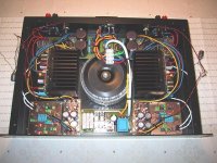
I've attached a photo of the amp as it looks right now. I'll try to talk you trough the picture.
The power input is in the back, in the middle, it goes through a simple spike protection (MOV resistor and RC network) and then to a slow start sircuit/remote start (middle front).
From the transformer the two PSU's are connected (placed on the back, you can se the two larger caps on each board).
From the each PSU power is fead to each poweramp (each amp is dual channel) and to the active filter PSU (on each side of the slow start unit). The powercables to the amps and to the filter PSU is tied togeter to reduse this loop area (one previous hum source).
Finally the active filters (front in the corners) are conneted to the filter PSU's.
The signal is taken from the RCA inputs in the back, to the active filters and then to each amplifier. The inputs of each amplifier have a "groundloop breaker", menaning that the input sircuit ground is taken from the filter ground and the input ground and the power ground is connected to each other by a series resistance (10ohm) parallelled with a cap (100n).
Direct connection of the amp input ground and power ground increases the buzz.
Finally the amplifier output signal goes through a speaker protection and delay (back in the corners) and then to the speaker terminal. The speaker ground is taken directly from the power PSU.
As seen on the picture I've tried using signal transformers to isolate the amp fron the input source, but it doesnt change things much, the sourse of the buzz is internally. Allso all units are now "flowating", not screwed to the chassis, to prevent the groundplanes of the different units to get in touch the screws, creating loops.
/Jesper
Attachments
Hi again,
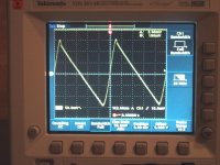
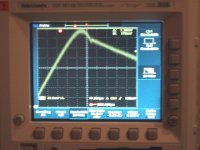
Hocked up an oscilloscope and took a look.
The buzz itself is to low to be seen on the scope, the scope itself is to noisy.
The picture attached is measured at the positive supply without music playing. You see some 250mV ripple, noting strange, but there is some overshot when the diodes turn off. I don't know if this may cause enough ground disturbanse to create buzz but is sure have som HF contents. A snubber would be usefull here.
/Jesper
Attachments
Hi there---I'm about to put cold water on your ideas...I'm very weary about using more that one mains tranny in any amp.........more magnetics equals more stray magnetic fields which doubles more problem loops and background noises. If one is using toroid cores (doughnut) and stuck with a particular size then rotating them can make a big difference with both channels listened to. (the windings are never wound symmetrical and under load the leakage inductance spews out the side of the winding which has poor coupling to the primary in to the circuits ajacent).
To get the real performance from a dual solid state amp does require pretty careful placement of the power supply components.There isn't a more critical place than the common of the smoothing caps and how that earthing is made in relation to the LS return, PSU connects and input stages. Both must be completely separate.
Some years ago I did such a beast .......with partial success. The S/N ratio was never as low as the manufacturer claimed.....but it was fine for live perf.
rich
Hi Rich,
I only have one tranny, but two PSU's (bridges and caps).
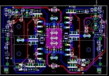
Right now I have the smoothing caps sitting on a farly large groundplane to which the LS return is fead, maybe I should try putting the LS return to the amplifier power gound point (which is very local, I've put lot of effort making it so). The PS + and - is very close to the local power ground point and fead directly to the tansistors with short leads. The input ground is then taken physically away from that local power ground of the amp and even isolated by a 10ohm resistor in parallell with a 100nf cap. The PSU connections is located in the center of the board and the inputs on the left and right edges. The input ground point and feedback ground is also very physically close.
I'll post an image instead...
/Jesper
I only have one tranny, but two PSU's (bridges and caps).
Right now I have the smoothing caps sitting on a farly large groundplane to which the LS return is fead, maybe I should try putting the LS return to the amplifier power gound point (which is very local, I've put lot of effort making it so). The PS + and - is very close to the local power ground point and fead directly to the tansistors with short leads. The input ground is then taken physically away from that local power ground of the amp and even isolated by a 10ohm resistor in parallell with a 100nf cap. The PSU connections is located in the center of the board and the inputs on the left and right edges. The input ground point and feedback ground is also very physically close.
I'll post an image instead...
/Jesper
Attachments
<Hi there ..I've got a sneaking suspicion (it's getting rather late) that you are using 10,000uF per rail smoothing cap.....for 500W p ch ?I would rate that value as the min ... I don't know what the o/p stage quies current is for such a beast, but probably around the 200ma ballpark..........the residual hum may orig from that unregulated + supply.... it seems to me that the amp grounds go round in a "circuit" around the tranny in which case you have to live with it or up the smoothing cap values......one old trick to find out if it is the tranny is to blame for the earth loop is to fire the amp up via a variac or variable voltage tranny and listen for the change with a 15% voltage reduction. Any change and the tranny is to blame.
rich
rich
Hi
It's actually 4*80W or something like that, so "only" a total of 320W. For that I use a 500VA tranny. And I use one PSU for each dual channel amplifier, so 10.000uF per rail for 160W and 2*50mA of cuesent current, the ripple due to that is only some 250mV.
I wouldn't be surprised if the remainder hum is from the tranny, picked up by the psu and signal cables and maybe even the boards. I'll try your variac test.. Maybe some day I'll get hold of some mymetal to sheild the tranny somewhat.
But for now I think I can live with the ramainding hum and start focusing on my other projects which is waiting, a preamp and a sub for instanse...
The sound is acutally quite good (despite the small hum)..
/Jesper
Basic hum problems in dual trans/mosfet amps are nasty......this isn't a particulary nice new years gift to sort out. I started by removing the input wiring and measuring afterwards......methodically.... even the end result was a compromise.
The real headache begins when one has actually improved the hum reduction and another problem re-emerges. For example; in my amp by breaking earth loops (to what I thought was ideal) I had ruined the crosstalk perf between A+B to roughly 15dB down on the ajacent channel. Put it simply, the test involves dummy loading the o/p of A, then applying 10Khz sine wave to A input until o/p near clips; S/C the B input and measure the residual volts coming out of B amp with a scope and compare with A. This is the standard crosstalk test and alot of amps fail this test due to bad wiring errors or wiring that has been moved to the wrong place.....check vice versa. Excessive crosstalk at HFreq is usually wiring placement sensitive and also exactly where the LS leads are. These much be carefully placed and not tie wrapped with any other wiring. The effect on audio quality is a pronounced loss of ambience with wide stereo placement.
rich
- Status
- This old topic is closed. If you want to reopen this topic, contact a moderator using the "Report Post" button.
- Home
- Amplifiers
- Power Supplies
- One transformer dual PSU's