I try to build a converter, but I am not sure how the connection is made from the output of PWM to mosfet. Would it require an isolator ? Can someone show me in diagram ?
The mosfet I used should be p-channel. And I need some suggestions on what mosfet I need, is RFP30P06 ok ? The incoming supply is 28V with switching frequency 100kHz.
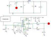
The diagram is as below, any problem with that ?
I am new to this design and here too. Hopefully I am posting in the right place. Appreciate and expecting any suggestions. Thanks.
The mosfet I used should be p-channel. And I need some suggestions on what mosfet I need, is RFP30P06 ok ? The incoming supply is 28V with switching frequency 100kHz.
The diagram is as below, any problem with that ?
I am new to this design and here too. Hopefully I am posting in the right place. Appreciate and expecting any suggestions. Thanks.
Attachments
Nobody is answering because your question is not answerable.
There simply isn't enough information to provide a meaningful answer.
May I suggest you use a reference design from one of the manufacturers instead?
Please note that there is limited competency in SMPS on this board - true some individuals are highly skilled but the traffic on SMPS is very limited.
Petter
Ok, will check it out.Circlotron said:Have a look at an IR2121 or an IR2125. Not sure which one but they are similar.

Yup, by first inverting it with another error amplifier (inverting amplifier -- positive input to ground)Circlotron said:Seeing your converter will have a negative output voltage, will the error amplifier input on the controller chip work ok with this?
Somewhat confusing circuit.
If u are looking for a step down conv,,,Try a single chip solution like MAX 724.
www.MAXIM-IC.Com
For MAX 724. i/p can go upto 40 Volts and O/p Variable can sink upto 5 Amps.
Or SG3524 (both o/p added for max duty cycle.and IR2110 or any high side driver.
If u are looking for a step down conv,,,Try a single chip solution like MAX 724.
www.MAXIM-IC.Com
For MAX 724. i/p can go upto 40 Volts and O/p Variable can sink upto 5 Amps.
Or SG3524 (both o/p added for max duty cycle.and IR2110 or any high side driver.
Your circuit looks ok to me. look up an 4n36 here:
http://www.fairchildsemi.com/ds/4N/4N36.pdf
Page 25 has a schematic how to connect an opto coupler:
http://focus.ti.com/lit/ds/slus565f/slus565f.pdf
http://www.fairchildsemi.com/ds/4N/4N36.pdf
Page 25 has a schematic how to connect an opto coupler:
http://focus.ti.com/lit/ds/slus565f/slus565f.pdf
Re: pwm
Thanks for the replies
Yup, 1 power ground and 1 signal ground. But .. why using isolator Both the grounds will be connected at a single point after all.
Single chip solution is good .. but .. ..
SG3525 featuring soft-start ..
Yup, I think I need a high side driver
Really !!!?!! Can you show me ?
Thanks for the replies
raypsi said:Your schematic shows 2 grounds, ya?
Yup, 1 power ground and 1 signal ground. But .. why using isolator
Both the grounds will be connected at a single point after all.sivan_and said:If u are looking for a step down conv,,,Try a single chip solution like MAX 724.
Or SG3524 (both o/p added for max duty cycle.and IR2110 or any high side driver.
Single chip solution is good
.. but .. .. SG3525 featuring soft-start ..
Yup, I think I need a high side driver
sivan_and said:Even the outputs can be connected directly to MOSFEt w/o isolator,if u r using SG3524 or TL494.Since the IC output transistors collectors and emitters are easily accessible,can be configured freely...
Really !!!?!! Can you show me ?
might want to look at this thread
http://www.diyaudio.com/forums/showthread.php?s=&postid=240888#post240888
http://www.diyaudio.com/forums/showthread.php?s=&postid=240888#post240888
Still not figure out the application for it yet, +/- 12V should be useful. Just try to build some converter myself. And to gain some experiences with it.
Input voltage is +25V .. might need zener diode or diode here.
Output voltage is -12V (require soft start ?). +12V is ok too.
Resistive load 15ohm. So, load current = 0.8A.
Mosfet p-channel IRF9540 ?
The values above are not fixed.
Vi = 12V Vo = 5V R = 10 ohm or 15 ohm
are fine too.
And, thanks for your responces
And to gain some experiences with it.Input voltage is +25V .. might need zener diode or diode here.
Output voltage is -12V (require soft start ?). +12V is ok too.
Resistive load 15ohm. So, load current = 0.8A.
Mosfet p-channel IRF9540 ?
The values above are not fixed.
Vi = 12V Vo = 5V R = 10 ohm or 15 ohm
are fine too.
And, thanks for your responces
- Status
- This old topic is closed. If you want to reopen this topic, contact a moderator using the "Report Post" button.
- Home
- Amplifiers
- Power Supplies
- PWM to mosfet - using isolator or ?