my suggestion to you young man, is to read Sanjay Maniktala's excellent series of articles on magnetics on the National Semiconductor website -- you have specified I(max) for your design, but I(min) is also critical -- Sanjay also did a webcast for Tech OnLine which was like going back and taking that E&M cours you shouldn't have slept through in college.
you will probably find that an LC filter on the output will be helpful (in fact, it is necessary). Bigger capacitors aren't better in this type of design -- at your switching frequency the ESL kicks in.
btw, Sanjay has just written a book on Optimization of SMPS -- like all technical books this one is pretty expensive.
more coming...
Sorry but I don't understand in this page anything, or maybe I found some other page, search of ["National Semiconductor" website SMPS] find a lot off them. in one I can make calculations but I think that there was onle low PW power sulies (very low power, ant low voltages).
maybe I just find not a right one site, o I don't undertant something.
can u give a link to page u are talking about?
maybe I just find not a right one site, o I don't undertant something.
can u give a link to page u are talking about?
Xformer Turns Question
After reviewing some literature at www.mag-inc.com and reading some other threads I am having difficulty calculating the number of primary turns the transformer should have...
http://www.diyaudio.com/forums/showthread.php?s=&threadid=30183&perpage=10&pagenumber=2
Here are my parameters:
Vin(min) = 10 Volts
B = 1000 Gauss
Ae = 15.5 cm^2 [mag-inc PN 46113 Ferrite: 2.4inch-OD 1.4inch-ID 0.5inch-Height]
F = 40 Khz
Here is the formula I have used...
Np = (10^8*Vin(min))/(4*B*Ae*F)
where:
Vin(min) = [volts]
B = [gauss]
Ae = [cm^2]
F = [Hz]
so...
Np = (10^8 * 10 Volts) / (4*1,000 gauss * 15.5cm^2*40,000Hz)
= 0.4 turns (!??)
Even if I round up I am still only at 1-turn...
What's all this 4-turn stuff everyone keeps talking about? Did I miss a (*10) somewhere?
Thanks,
-=Randy
need help
I think many SMPS expart are visited here. I have a some prob about SMPS . U can red details : please visit this
http://www.diyaudio.com/forums/showthread.php?s=&postid=517611#post517611
Threat # 177
any one give me answer about my question. I am very new about circuite making.
sorry for posting this thread.
Regards
jackinnj,
Thanks for inquiring about my progress. As of now the SMPS is on hold because I do not have the capability to do double sided boards with plated through holes. I found a board house but for the size of the board they are going to charge $78.00 for 2 boards. Since xmas is coming up funds are a little short. It will be a week before I can send it off.
This idle time has not been wasted as I have been using the time to design the preamplifier and 500-W class-g amplifier stage.
I will post pictures of things as I get them done.
When its all said and done I plan on setting up a website like rod-elliot where he shows the schematic / tutorial.
Thanks again for your help!
Randy
Hi
I finally got around to rebuilding the switching power supply and here is what happened.
30OHM -- 333 Watts [~100 Volts RMS]
15OHM -- 602 Watts [~95 Volts RMS]
6OHMS -- 937.5 [~75 Volts RMS]
At the first two points the power supply ran continuously, but I got greedy at the last point and as a result it only lasted about two seconds and several of the MOSFETS finally blew...
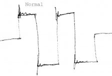
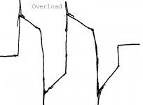
Just out of curiosity I was wondering what you guys think went wrong? The scope probe was connected directly to the output of the transformer [before rectification] and under normal operation I measured a decent looking square wave at the first two load points. However, when I placed a 6OHM load across the output and turned things on the square wave looked terrible...
At this power level would you attribute this to core saturation?
It was pretty spectacular... Huge amounts of smoke came rolling out of the power supply and than a small fire started...
Since I do not have the ability to save scope images to my computer I made a drawing of the waveforms. [xformer output] of what the waveform looked like when it was running fine and also during overload.
Thanks!
Randy
I finally got around to rebuilding the switching power supply and here is what happened.
30OHM -- 333 Watts [~100 Volts RMS]
15OHM -- 602 Watts [~95 Volts RMS]
6OHMS -- 937.5 [~75 Volts RMS]
At the first two points the power supply ran continuously, but I got greedy at the last point and as a result it only lasted about two seconds and several of the MOSFETS finally blew...
Just out of curiosity I was wondering what you guys think went wrong? The scope probe was connected directly to the output of the transformer [before rectification] and under normal operation I measured a decent looking square wave at the first two load points. However, when I placed a 6OHM load across the output and turned things on the square wave looked terrible...
At this power level would you attribute this to core saturation?
It was pretty spectacular... Huge amounts of smoke came rolling out of the power supply and than a small fire started...
Since I do not have the ability to save scope images to my computer I made a drawing of the waveforms. [xformer output] of what the waveform looked like when it was running fine and also during overload.
Thanks!
Randy
Attachments
Randy, do you want to say that now, after rebuilding, you can normally obtain over 600W output power?
I reviewed your posts and I think that in previous revision you had similar problem to what I experienced once (I wonder that other guys didn't mention it).
It is about transformer "leakage inductance": it is quite difficult to make this parasitic parameter negligibly low. That is, primary leakage inductance forms quite significant parasitic spikes at the moments of FET turn-off. This effect is clearly seen with oscilloscope. Then, with increasing output power, spikes become even higher, because leakage inductance stores more energy (it is some proportional to magnetizing inductance energy and thus to output power) - and, oops! - at some moment they exceed FET voltage rating, thus causing FET channel self-induction and avalanche breakdown. Single pulse avalanche sustainable energy is another seldom mentioned parameter that is usually specified in datasheets. In reality, up to some point FETs continue to work in this mode but dissipate the most of stored energy in leakage inductance (yeah, they become heating much more!)
So, I also tried once 40V type (maybe IRF2204) with 15V battery converter and couldn't get any decent power from it. After I found a matter of problem and replaced those expensive IRF2204 with cheap IRFZ44 (60V type), it fully helped.
So if you cannot afford to design special "low-leakage" transformer (man, that's not easy") ), you better continue with those IRFP054
), you better continue with those IRFP054
Concerning your last experiment, - that's a strange effect. If you still use that 2-inch core for transformer - I would say it should withstand 1kW power thru it for at least a few minutes, until overheat. What is your primary side power supply?
I reviewed your posts and I think that in previous revision you had similar problem to what I experienced once (I wonder that other guys didn't mention it).
It is about transformer "leakage inductance": it is quite difficult to make this parasitic parameter negligibly low. That is, primary leakage inductance forms quite significant parasitic spikes at the moments of FET turn-off. This effect is clearly seen with oscilloscope. Then, with increasing output power, spikes become even higher, because leakage inductance stores more energy (it is some proportional to magnetizing inductance energy and thus to output power) - and, oops! - at some moment they exceed FET voltage rating, thus causing FET channel self-induction and avalanche breakdown. Single pulse avalanche sustainable energy is another seldom mentioned parameter that is usually specified in datasheets. In reality, up to some point FETs continue to work in this mode but dissipate the most of stored energy in leakage inductance (yeah, they become heating much more!)
So, I also tried once 40V type (maybe IRF2204) with 15V battery converter and couldn't get any decent power from it. After I found a matter of problem and replaced those expensive IRF2204 with cheap IRFZ44 (60V type), it fully helped.
So if you cannot afford to design special "low-leakage" transformer (man, that's not easy
), you better continue with those IRFP054 Concerning your last experiment, - that's a strange effect. If you still use that 2-inch core for transformer - I would say it should withstand 1kW power thru it for at least a few minutes, until overheat. What is your primary side power supply?
SMPS failures
Hi Randy
Sorry to hear of your BANG. Some thoughts on this:
In a raw push-pull power supply one has to be very careful of what is called 'flux walking', which can easily culminate in saturation and BANG. No two MOSfets or their drive circuits are identical to the point where one can assume their volt-seconds contributions will be exactly the same.
Now you say your maximum duty cycle (for each push-pull arm) is 40%. Of the total time, yes. But looking at your waveform, which makes sense i.t.o. my recollection of the SG3525, the 40% is a duty cycle of the total switching period, ie each arm of the push-pull is being driven to 40% of the total, so the transformer is powered for 80% of the total time. This is fine provided the volt seconds of one pushpull arm exactly cancel out the volt seconds of the other, which they won't do in your configuration. So the nett flux starts slowly increasing. This won't be a problem while there is still sufficient dead time for the core to reset this small V.s offset, but as you increase the load, the offset will increase until it is too large to be reset in the deadtime. Then it spirals rapidly outr of control, the core saturates and BANG

 This holds for any core, gapped or not. An airgap is not a prophelactic against saturation.
This phenomenon of flux walking in push-pull power supplies is why it's common practice to employ a strategy like peak current mode on these PSU's. This ensures both arms of the push pull are driven equally and flux walking won't occur. Furthermore, in my opinion it's imperative to have cycle by cycle current limiting in any SMPS, push-pull or otherwise.
Now in your case you'd have to rework the entire design around a different control chip but you've indicated the PSU has abundant spare capacity, so what you could consider is restricting the duty cycle of each arm of the push pull to 25% or less so that there is sufficient core dead time to reset any V.s offsets that occur.
Your circuit isn't in front of me now and if I go back to it to check out anything I'll lose all this stuff I typed, but I don't remember seeing there to be cycle by cycle current limit mechanism. I really would strongly recommend you add one in if there isn't one already.
I hope this helps.
Regards
John
Hi Randy
Sorry to hear of your BANG. Some thoughts on this:
In a raw push-pull power supply one has to be very careful of what is called 'flux walking', which can easily culminate in saturation and BANG. No two MOSfets or their drive circuits are identical to the point where one can assume their volt-seconds contributions will be exactly the same.
Now you say your maximum duty cycle (for each push-pull arm) is 40%. Of the total time, yes. But looking at your waveform, which makes sense i.t.o. my recollection of the SG3525, the 40% is a duty cycle of the total switching period, ie each arm of the push-pull is being driven to 40% of the total, so the transformer is powered for 80% of the total time. This is fine provided the volt seconds of one pushpull arm exactly cancel out the volt seconds of the other, which they won't do in your configuration. So the nett flux starts slowly increasing. This won't be a problem while there is still sufficient dead time for the core to reset this small V.s offset, but as you increase the load, the offset will increase until it is too large to be reset in the deadtime. Then it spirals rapidly outr of control, the core saturates and BANG
This holds for any core, gapped or not. An airgap is not a prophelactic against saturation.This phenomenon of flux walking in push-pull power supplies is why it's common practice to employ a strategy like peak current mode on these PSU's. This ensures both arms of the push pull are driven equally and flux walking won't occur. Furthermore, in my opinion it's imperative to have cycle by cycle current limiting in any SMPS, push-pull or otherwise.
Now in your case you'd have to rework the entire design around a different control chip
but you've indicated the PSU has abundant spare capacity, so what you could consider is restricting the duty cycle of each arm of the push pull to 25% or less so that there is sufficient core dead time to reset any V.s offsets that occur. Your circuit isn't in front of me now and if I go back to it to check out anything I'll lose all this stuff I typed, but I don't remember seeing there to be cycle by cycle current limit mechanism. I really would strongly recommend you add one in if there isn't one already.
I hope this helps.
Regards
John

Update
Hey,
It turns out I was using the wrong MOSFET... I was using a 30-amp rated part instead of the correct IRFP054N [70+ amps per device] I feel like such an idiot for doing that!
Anyway, after switching to the real mosfets I was able to achieve 853Watts for a little over 5 minutes. I had to stop because my 10ohm 500watt dummy load stared to smoke. After five minutes of 853 watts the torroid measured in at 67degC according to the thermistor I glued onto it.
On the final version Im thinking of putting a thermistor on both the torroid and mosfets and shutting down the controller once the parts reach a certain temperature. First, is this a stupid idea and if not how high should I allow the torroid to get before I shut it down? The datasheet says the curie temp is around 200degC but i wouldnt want it to get anywhere near that high. I'm thinking on the order of 100degC for both the MOSFETS and the TORROID.
Thanks!
-=Randy
Mankato MN
To John Hope: we recently discussed the issue that you mention here at power supply forum in the thread named "Staircase saturation in push-pull SMPS".
But I have to say once again, in real life this is far NOT the main problem about push-pull supply even with duty cycle of 47-48% of period and power rating 2 times higher than Randy tries for similar core (1600W power, toroid reaching 120 degC in 5 minutes - my own experiment).
To Randy Knutson: now it's clear about that strange waveform during overload.
Were there faked FETs or just weaker type?
Transformer temperature of 67degC in 5 minutes tells me that you have additional power margin, actually 850W for 2-inch core is really not a limit.
Usually, you can allow maximum transformer temperature as high as 140degC, provided wire insulation allows this and you use solder with higher melting point
Huh?
Lets see we are listening to music, lets say you like highly compressed rock music. So we have a touch over 900 watts average with 10:1 peak to average ratio or 9000 watts peak.
Living room or stadium?
I don't think your power supply needs the bigger FET but that's just me.
Current limiting will likely save you a call to the fire department at some future date.
Living room or stadium, maybe you've heard that loud noises drive out termites? I recommend very good speakers and probably ear protection - enjoy
To hermanv: you are quite right about full power test; there is no need even for half power during music signal operation. In commercial production, we still need to pass a standard 5-min full RMS power test for every amplifier design, so I'm just used to test everything at full power for at least 5 minutes
Regarding current limit, usually they implement overcurrent protection (OCP) into amplifier and send OCP signal back to power supply to switch it off/cycle. Strictly speaking this is not quite correct concept; especially in mains power supply I prefer to sense primary switches current for OCP.
Regarding current limit, usually they implement overcurrent protection (OCP) into amplifier and send OCP signal back to power supply to switch it off/cycle. Strictly speaking this is not quite correct concept; especially in mains power supply I prefer to sense primary switches current for OCP.
Over current
Fuses are cheap, not as elegant or as fast as fancy electronics but they beat molten copper and FETs that burn clear through a heat sink.
Circuit breakers (fast acting) are OK too but cost more and almost always slower but they do have that magic reset feature. The right ones can double as an on/off switch thereby recovering some of the cost.
I hadn't read enough of the posts to realize we were talking pro music power amps. For those 900 watts is not even in the big leagues
Fuses are cheap, not as elegant or as fast as fancy electronics but they beat molten copper and FETs that burn clear through a heat sink
.Circuit breakers (fast acting) are OK too but cost more and almost always slower but they do have that magic reset feature. The right ones can double as an on/off switch thereby recovering some of the cost.
I hadn't read enough of the posts to realize we were talking pro music power amps. For those 900 watts is not even in the big leagues
- Status
- This old topic is closed. If you want to reopen this topic, contact a moderator using the "Report Post" button.
- Home
- Amplifiers
- Power Supplies
- Any Switching Power Supply Experts???