I am attempting to modify a 240V Akai Sampler I bought from someone in Germany to USA 120V standard. Yes, I know I could use a step down transformer. But that wouldn't be any fun.
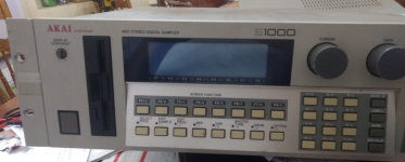
Akai S1100 Sampler
It has two power supplies. One is a switch mode power supply that converts 120V or else 240V to 5V DC and 12V DC power. There is a jumper/plug that you flip around to change it from 240V to 120V. That was easy.
However, there is also another power supply with a transformer that provides AC power to the motherboard and digital output board and I believe also to the LCD. Do most LCD's run on AC power or DC power?
Anyways, the transformer is only outputting 7.2VAC and I believe that is about half of what it is supposed to be outputting. One other person who has the native 120V model of the Akai S1100 measured theirs and told me that they are getting about 16VAC. However, another person told me they put in a 15VAC transformer and that worked. So the first problem I have is not knowing whether I need 14.4VAC, 15VAC, or 16VAC coming out of this transformer. I'm guessing that 14.4V is not a standard and that 15VAC is the likely safe bet and that it would be safer to underpower the unit than to overpower it.
Also, the current transformer has a positive and negative going into it, but two positive (white) wires coming out of it and one black wire. This does not seem to be the standard for transformers. The two white wires and one black wire all go into a single plug that plugs into the motherboard.
Most of this unit operates off the 5V and 12V power supply. Everything seems to currently work and I ever get test tones, however, I cannot see the display but can confirm it is getting some power (though likely not enough to display readable text). I confirmed the LCD works in a different unit.
So here's how you could help me:
Refer me to any projects where people converted 240V audio units from Europe to 120V USA standards.
Refer me to suppliers of transformers that convert 120VAC to 15VAC. Mouser electronics? Other suppliers?
Warn me of anything you believe I am overlooking, flaws in my thinking...prevent me from blowing up my unit by making a rookie mistake.
Toss me some ideas why a plug would have three wires (2 white, 1 black) coming out of a transformer instead of just one white and one black.
Convince me to give up this experiment and just buy a bulky step down transformer. 100watts? or 500watts?
Thanks in advance.
Welcome to diyAudio ")
Conversions from 240 to 120 or vice versa usually entail checking if the original transformer has multiple primary windings that can be reconfigured. If there are just two wires to the primary, or just two connections to the primary then its single voltage only. If it has 4 (or sometimes more) then it may be configurable for different voltages.
If you power an unconnected transformer via a bulb limiter (use a small 15watt mains filament lamp... or any low wattage) then you limit the risk of damage as you explore any possible connection possibilities.
Suppliers depend on where you are globally but yes, Mouser, RS, Farnell and Digikey are all big names.
If a lead has three wires coming out of a transformer then that suggests a winding with tappings (such as 8-0-8 vac for example). It very common to see that. If its a primary winding then it might be 0-120-240 Vac.
Transformer voltages are rated at full load current and as such it is common to see voltages in excess of the rating at low currents. This figure is the 'regulation' which should be quoted in the data sheet as a percentage. Small transformers are worse for having poor regulation.
Most important thing is to stay safe. Use a bulb tester when testing/exploring any unconnected transformer.
LCD screens have a variety of voltages and timing signals needed that are derived from sophisticated electronics, and not just a simple supply. So you need to power the LCD board using the correct basic input voltage so the electronics can do their thing.
Mooly, you are very helpful.
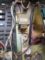
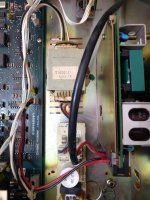
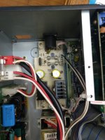
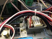
I attached some pictures of what I'm dealing with. One is an S1000 Japanese version which is rated at 100V. It is marked as S1000(J). The other picture shows the S1100 EVBS transformer in the S1100 which is the 240V version. I'm more interested in converting the S1100 240V version first.
You can see pictures of the two white wires and black wire coming out of the transformers. Notice that in the older S1000 the output from the transformer connects directly to the motherboard. In the newer S1100 it connects first to the digital output board and then has three connectors connecting back to the motherboard (probably two of them are data and one power).
The S1000(J) transformer does appear to be configurable. The power wires connect to the bottom of the transformer but there are small copper leads going into segregated partitions in the top of the transformer. I have no idea how to configure these and would feel more comfortable just switching them out with new ones.
Is there any such thing as an "audio grade" transformer? I would imagine that a good transformer in audio equipment does not interfere with the audio signal, does not produce any ground hum, is quiet, and possibly has less variance in output (more steady). I don't know the correct terminology to describe these things, but imagine that quality varies from one transformer to another based on brand and build quality and design.
If I buy a transformer with only one white wire and one black wire as outputs, and split the white wire into two wires, am I risking any damage? My guess is no, because splitting a wire is just like splitting power out of an AC outlet by utilization of a power strip. However, I'm wondering if a transformer in this example effects that.
This is a learning process for me, but I find it all very interesting and I have loads of vintage audio equipment so I'm going to have to learn more to keep this old equipment alive. Thanks!
Attachments
Its never easy working from pictures
The EVBS version seems to feed a small board with a bridge rectifier and two reservoir caps. That makes sense with regard to the three wires as it suggests a split secondary winding giving perhaps 15-0-15 vac. That's the most common form seen in most equipment although we do need to know the voltage.
Things to check.
1/ Does the black wire go to ground (perhaps connected to chassis) ? I'm guessing it also goes to the junction of those two yellow caps which will probably appear to be in series, with the junction of them being ground.
2/ Measure the AC voltage from the black lead to each of the while ones. Is that where your 7.4 volts comes from. You should therefore have around 15 volts AC between the two white wires.
3/ What is the voltage rating marked on those two yellow caps ? That sets an upper limit for us to work to.
4/ The two devices bolted to the heatsinks. What are they marked as ? Is one a 7812 or 7815 and the other a 7912 or 7915 ? or are they something different ?
Its a pretty safe bet that if you read 7.4 volts AC between black and either white wire that we are looking at a 15-0-15 transformer.
It looks quite a good quality transformer having a copper 'belly band' around it for low leakage... a typical Japanese type of construction. For low impedance line level circuitry its not such a big deal though.
The S1000J unfortunately doesn't look configurable. The two thin wires on the transformer will be for the primary, the two thicker ones look to be for a thermal fuse embedded in the windings/construction of the transformer. So ultimately it is in fact a single voltage primary
We also have to guess at the rating (current or VA) of the transformer. A good clue can be to measure the weight and compare to new ones.
When looking at new transformer you can choose either a split winding as this appears to be or one with dual secondary's (4 wires) where the two are simply connected in series with the centre tap becoming the centre point... all standard stuff.
You also need to measure how much space you have available and decide what type of transformer you might be looking at... toroidals are the most common and cost effective these days.
Examples might be like this:
https://uk.farnell.com/multicomp/mcta060-15/transformer-toroidal-2-x-15v-60va/dp/9530436
http://www.farnell.com/datasheets/2...46.327530231.1534874973-1577493477.1533651991
....needs 50W.
...Do you think a 30VA 1A transformer will work?
50 Watts at 15V is 3.3 Amps.
A 30VA 1A transformer is 30 Volts (you want 15V).
Can't be too hard to find a 15V 3A transformer.
Attachments
My advice is going to go against the grain here.
1. Put the SMPS back to the way you found it
2. Use an external step-up transformer.
I understand it's possible to modify this device internally, but the easiest, cheapest, and most efficient way to do this job, would be to simply use an external step-up transformer, and get on with life. Also, this will do the least harm, in case the new transformer introduces hum or other issues to the sampler.
I bought a 100W step up transformer at a travel store for about $30, and I use it for powering euro equipment. I also have a 500VA unit I got at Fry's, I use for a big tube amp.
Last edited:
- Status
- This old topic is closed. If you want to reopen this topic, contact a moderator using the "Report Post" button.
- Home
- Amplifiers
- Power Supplies
- 120V AC to 15V AC Transformer for Akai Sampler