I found this site last week and it brought back memory of conversation that I had with Eva. There we also talked about saturation of different magnetics and how to test for that.
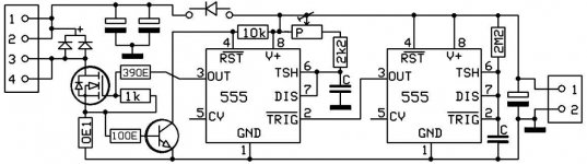
I found this circuit very simple and I ptu it in LTspice to simulate it. It worked as expected, but couldn't show me real inductor saturation as one would get with real inductor.
I looked around, what components I had laying around. I had everything I wanted. I even started to place components on protoboard, but I soon saw, that it will be a lot of work even for such simple schematic.
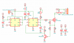
For some time I wanted to use Kicad, so that is what I did. I knew there were some pretty cheap places I could have my board done. Looking on pcbshopper, I saw many options, but most were either slow shipping or expensive. All but one. Allpcb had low price and DHL shipping, estimated delivery in 8 day or under. I sent my gerbers to them, payed with paypal and that was it, very simple. Only 5 days later, I get package.
Box

PCBs, I paid for 5, got 6 which is always nice

Top and bottom, pcbs came out perfect

Components mounted

Current in some random inductor from pc supply. Saturation "knee" is around 16-17A.

Since you know the current and you can read out the time it takes to get to that current and you know voltage applied on this inductor, then you can calculated its inductance L with this formula:
I found this circuit very simple and I ptu it in LTspice to simulate it. It worked as expected, but couldn't show me real inductor saturation as one would get with real inductor.
I looked around, what components I had laying around. I had everything I wanted. I even started to place components on protoboard, but I soon saw, that it will be a lot of work even for such simple schematic.
For some time I wanted to use Kicad, so that is what I did. I knew there were some pretty cheap places I could have my board done. Looking on pcbshopper, I saw many options, but most were either slow shipping or expensive. All but one. Allpcb had low price and DHL shipping, estimated delivery in 8 day or under. I sent my gerbers to them, payed with paypal and that was it, very simple. Only 5 days later, I get package.
Box
PCBs, I paid for 5, got 6 which is always nice
Top and bottom, pcbs came out perfect
Components mounted
Current in some random inductor from pc supply. Saturation "knee" is around 16-17A.
Since you know the current and you can read out the time it takes to get to that current and you know voltage applied on this inductor, then you can calculated its inductance L with this formula:
I checked this on few inductors, all were calculated just about the same as what LCR meter measured, that is great! And now I also know, when there is saturation and how that point looks like. Different material will behave differently!L = Vs * Δt / ΔI
Last edited:

Reminds me of when I first started with class d designs.
I was a bit naïve concerning inductors and just put in a power inductor on the output filter of my amp. It got to about 120 degrees c !
I was advised to use a different core like the t106-2. I wound my own inductor with that core and it worked great. It barely got warm.
I was a bit naïve concerning inductors and just put in a power inductor on the output filter of my amp. It got to about 120 degrees c !
I was advised to use a different core like the t106-2. I wound my own inductor with that core and it worked great. It barely got warm.
Here is a Power Inductor Tester that I have been using. It is a real work horse and I have a built in current limited, selectable power supply for small, med and large inductors. The attachment is a great tool on using the tester also.
Duke:
Power inductor tester
Duke:
Power inductor tester
Last edited:
Nr.6 is missing
Here it is, at least most of it
Mona
You are right, but you already posted one

I will put whole project up, probably on my site with gerbers and files from kicad
Attachments
Yes, indeed, that was one of the first things we talked about back in the day. That seem to be, to me, very useful, but not at that time, had to figure out many other things before that. But for this one I didn't want to build another pwm generator wit SG or TL, while it would work as well as this, I wanted to build alternative because... well 555s
Next challenge is how does one using a micro-controller integrate between two points from start to end of the current ramp, I would like to try that, without a scope a scope, this is for geting some dynamic statistics from the ramp sample waveform like Inductor current over time, current saturation point i.e the point where the ramp starts to show an irregular what looks like a tangent.
That will be really great those new 16f PIC's (10-bit) can do it, $2 part and some simple code.
Last edited:
I think that can be big problem to solve. Since you are looking at graphical representation of current, *you* can process a lot more data, like:
- is there linear region?
- is current exponential from the start? (depends on material)
- how sharp is the 'knee'?
Things like that would be hard to program into any micro.
Scope alike kit you can get cheap this days, even used scopes. Even analog scopes will work with this.
But I would like to see, if it is that simple or not
- Status
- This old topic is closed. If you want to reopen this topic, contact a moderator using the "Report Post" button.
- Home
- Amplifiers
- Power Supplies
- Power inductor saturation checker