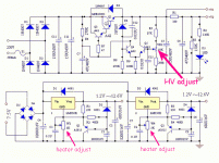
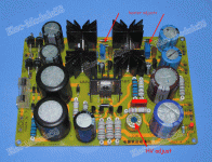
Hey all, I'm putting together a cheap 6j1/ef95 preamp. I have seen this board mentioned by a few users as being a good one so I took the plunge. I ordered the preamp PCB, and the recommended dual voltage rectifier board (AC to DC convert) which was listed on the
preamp eBay listing:
Preamp PCB: 6J1 Valve Pre-amp Dual Channel Tube Preamp Preamplifier Board / PCB EWY | eBay
Power rectifier board: LM317 Tube PSU High and low voltage soft start Amplifier power supplier Unit | eBay
The preamp needs to be powered with: 6.3v DC for the filament, and 275v DC for the high voltage.
The questions:
1. How do I adjust the "high voltage" output on the rectifier board? I see there are two small blue POT which can be adjusted, but those are for dual 6.3v outputs (marked 'A' and 'B' on the PCB itself). So it looks like I can adjust both 6.3v outputs, but I see no way of doing this with the high voltage output side??
2. a) What would be the ideal voltage to get when I purchase a transformer? When converting from AC to DC, do you end up with a higher voltage DC output compared to what you input in AC? (example Input 275v AC output 300v DC)
b) Would a 275v AC + 6.3v AC transformer work correctly, or would there a "loss" of voltage on the rectifier output compared to the input?? Examples: Input 275v AC output 260v DC (loss), or Input 275v AC output 275v DC (zero loss/gain)
c) If there is expected to be less DC output compared to the AC input, I assume it would be a better idea to get a transformer that is slightly OVER voltage spec (example 290v AC).
Thank you very much guys!! I hope one of you fine members can help me figure this out.
THANK YOU VERY MUCH!! I was wondering what that circular blue thing was. Very much appreciated.
The product page says it uses 250v AC input, with adjustable 115v - 320v DC output. So I assume that the rectified DC output voltage is indeed higher than the input voltage. Meaning I can use a 250v + 6.3v transformer with no problem? I might want to run the filament @ slightly higher 6.5v - I think this should still be fine?
I was starting to think that I would have to use a higher voltage rating to account for losses during rectification. (I know very little about AC electricity obviously!)
Seriously love this forum. You guys are awesome!
Last edited:
250V AC will rectify-out to 350V of DC. Cap-input power supply is a peak catcher.
Minus losses.
It seems reasonable it could turn 250VAC into 300V-340V DC and regulate that to 275V DC.
OK that makes sense finally! I kept getting hung up on the fact linear regulators can't boost the voltage so was unsure where all that extra voltage would come from!
So in this case, it works out roughly like: 250v(ac) x 1.4 = 350v (dc)
Thanks so much! I will order up a transformer and get this thing out together
- Status
- This old topic is closed. If you want to reopen this topic, contact a moderator using the "Report Post" button.

