Hi folks
I have three boards I'm going to use and they each have 5v DC inputs with onboard AMS1117 regulators that reduce the voltage to 3.3v.
What would be the best way to provide power to these boards - to feed them 5v from a regulator and bank of smoothing caps? This would be two stages of regulation, is this a good thing or bad?
Or would it be better to remove/bypass the onboard AMS1117 and associated SMD caps and feed the board from a 3.3v regulator and bank of smoothing caps - a single stage of regulation.
HI Ian,
A 5V-to-3.3V converter is normally used because you already have a 5V line and further need a 3.3V supply voltage. Then, this converter solves that problem using the existing 5V supply.
If, you have no exiting 5V supply (and need none) but some 5V-to-3.3V converters, you can choose between the two option you mention:
1) Make a 5V supply and cascade the 5V-to-3.3v converters to the 5V output, or
2) make a 3.3V supply from scratch and forget about the 5V-to-3.3V converters.
Both solutions will work. The 3.3V is most likely intended for a digital circuit where the ripple demands are moderate.
As a small advantage for option 2) it can be said that it increases the input voltage margin because the difference between the input voltage and output voltage (3.3V) is higher than for option 1).
Last edited:
Merci beaucoup!
I'm replacing the CS4344 DAC board in my DIY DAC, which runs of a single rail 5v supply with a three board solution that consists of:
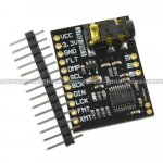
PCM5102A DAC board that has i2S input and runs off 3.3v, no on-board regulation:

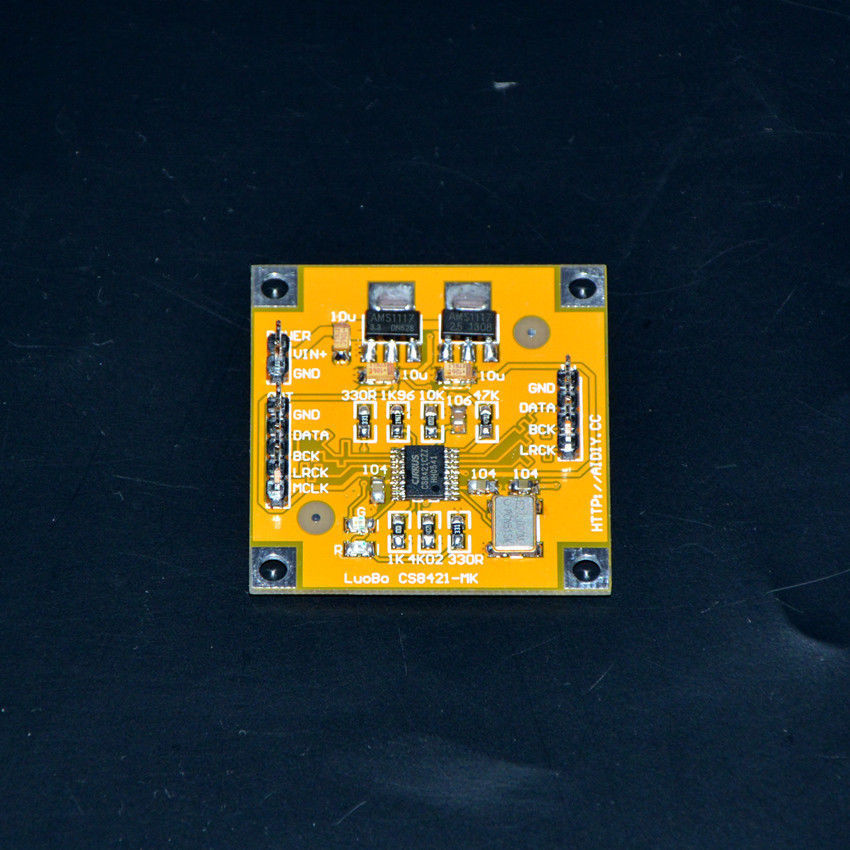
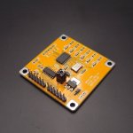
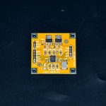
CS8421 sample rate converter board that runs off 5v wth an on-board AMS1117:
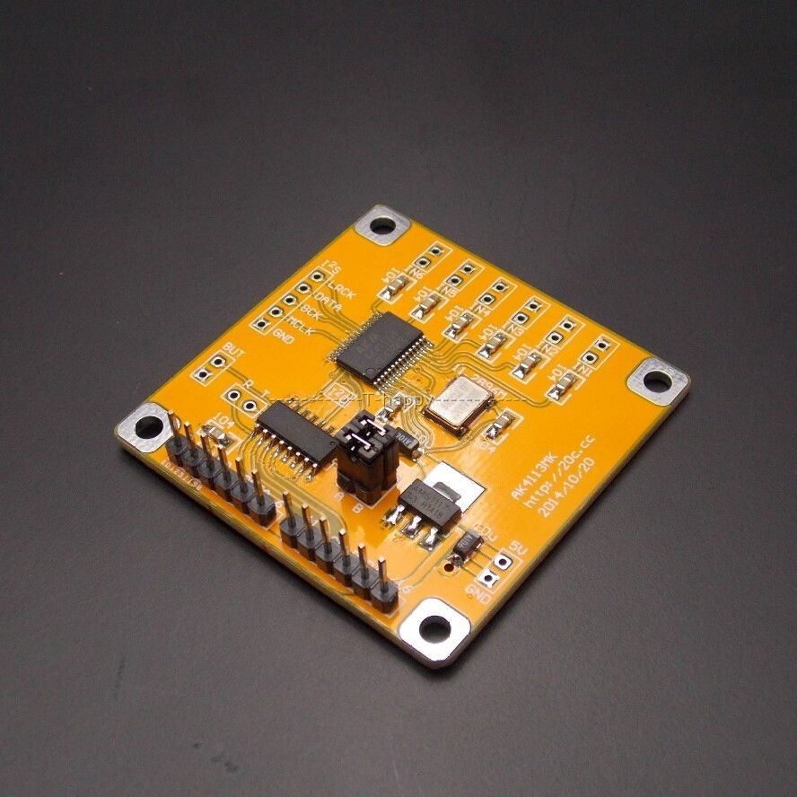
AK4113 SPDIF to I2S board that also runs off 5v and has an on-board AMS1117:
The transformer I have been using has a 9v-0-9v output and I'm running that into a rectifier then a LM317/LM337 regulator board, then a bank of smoothing caps, this gives a 5v supply to the CS4344 board.
I have another, identical transformer so I was thinking of replicating the existing setup with rectifier then LM317/LM337 board and banks of smoothing caps, I already have all the parts to do this.
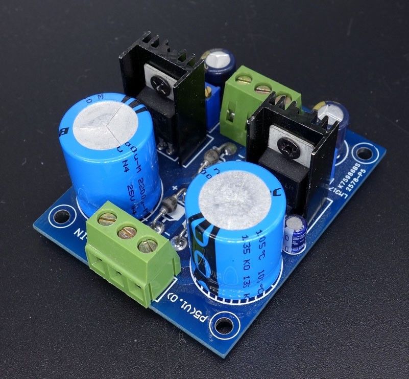
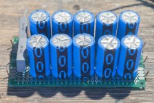
dual cap bank I made from 10 Phillips 16v 2200uF and 2 Epcos 400v 1000pF:

LM317/LM337 regulator with on-board diode bridge rectifier:
I suppose it's a bit overkill to power these boards that way but they do say a good, clean PSU is one of the most important aspects of a piece of audio equipment. I have another transformer-rectifier-LM317/LM337-bank of caps that is powering the analogue output stage.
I'm replacing the CS4344 DAC board in my DIY DAC, which runs of a single rail 5v supply with a three board solution that consists of:
PCM5102A DAC board that has i2S input and runs off 3.3v, no on-board regulation:
CS8421 sample rate converter board that runs off 5v wth an on-board AMS1117:
AK4113 SPDIF to I2S board that also runs off 5v and has an on-board AMS1117:
The transformer I have been using has a 9v-0-9v output and I'm running that into a rectifier then a LM317/LM337 regulator board, then a bank of smoothing caps, this gives a 5v supply to the CS4344 board.
I have another, identical transformer so I was thinking of replicating the existing setup with rectifier then LM317/LM337 board and banks of smoothing caps, I already have all the parts to do this.
dual cap bank I made from 10 Phillips 16v 2200uF and 2 Epcos 400v 1000pF:
LM317/LM337 regulator with on-board diode bridge rectifier:
I suppose it's a bit overkill to power these boards that way but they do say a good, clean PSU is one of the most important aspects of a piece of audio equipment. I have another transformer-rectifier-LM317/LM337-bank of caps that is powering the analogue output stage.
Attachments

Hi Ian,
It seems that more of the boards use 5V as well. Then, I would use the cascaded solution.
Even the PCM5102A DAC board seems to have a "Vcc" terminal, could that be 5V?
Why do you need LM337? Do you use a negative voltage for any of the boards?
Your 10x2200uF board is definitely overkill for such moderate consumption.
Well, I'm new to all this, it's my first DIY project, so I won't claim to know what I'm doing.
I was advised to chose the LM317/LM337, the reason given to me was that it was a better regulator than most.
I bought a bag of 20 of those 2200uF caps on ebay dirt cheap, they were under 3ukp inc postage, so I figured why not use them all, thinking that the more caps in the bank, the smoother it would make the output.
The only part of my DAC that uses a negative voltage is the output buffer, which has 15-0-15 dual rail inputs, to power this I am using a small toroidal transformer that has 2x18v outputs.
One question about the other transformers I have, they have three wires for the output which I measured with my multimeter as 9v-0-9v. Can I use this to power two of my 5v boards? The output from the transformer goes into an LM317/337 board which has three outputs - positive, ground and negative, these are connected to the capacitor bank. Can I power one board using the positive and ground connections and a second board using the negative and ground connections?
Please feel free to criticise, as I said, I'm very much a beginner and value criticism as it will help me learn.
The more capacitance you use, the more stress will be on rectifiers and regulators during power on because of inrush current. Maybe the regulators will switch into protection immediately - nothing to win here. Personally I wouldn't use LM317/LM337 for such an application either, but that's kind of taste.
Also in my opinion I wouldn't but caps via ebay/alibaba/... because the risk of getting fake ones is there. I have seen some big caps in the past that were only "cases" and inside the 2200µF-one was an small 100µF one with lower voltage-rating for example.
Also in my opinion I wouldn't but caps via ebay/alibaba/... because the risk of getting fake ones is there. I have seen some big caps in the past that were only "cases" and inside the 2200µF-one was an small 100µF one with lower voltage-rating for example.
Last edited:
I'm afraid I know nothing about inrush current, is there a modification I could make to avoid this?
Again, I know very little about what regulators are available, what type would you suggest for this application?
On caps, I will only buy from UK sources, sellers that are either brick and mortar stores that also sell on ebay, mostly, for the reason you say - the risk of getting fakes, China fakes everything, they even make fakes of their fakes.
Hi Ian,
I am just trying to get the overview so I can give you good advise.
You need +/-15V for the output buffer but that has already been taken care of with another power supply board and an 18-0-18 Vac transformer.
It seems that what you need now is a power supply that can deliver +5V and +3.3V. You have at least one 9-0-9 Vac transformer and that one can be used. A 9-0-9 transformer is intended for a symmetrical voltage but it can also be used to make only a single voltage. To make only one voltage, you need two diodes and not necessarily a rectifier bridge. You can use a rectifier bridge and then you get both a positive and a negative voltage. Then, you only use the positive voltage.
You cannot use a symmetrical +5V/-5V supply to feed two 5V boards such that you use the +5V and ground for one board and ground and -5V for the other board. The voltages are not “floating” with respect to one another and your ground potentials will be different.
For your needs, the LM317 should do fine. Your caps are probably fine as well. China does not “fake everything”. Most consumer electronics today is made in Asia, often China. It does not mean that such apparatuses are constructed solely from fakes and do not work well. China has got a lot of less known component brands and manufacturers – some quite good, other less good. It is rare, the product pretends to be from a brand known in the western world but is actually a poorly performing copy. The brands in the western world produce a large part of their components in Asia and this is one reason why that market is flooded with components at attractive prices. Also, brands known in the western world sometimes have components made by manufacturers that also supply local brands. Some components may not have been intended to be sold in the western world at least not under that brand, or may have failed in some test, that is another matter. Occasionally, you may run into a regular “scam” as mentioned in a posting, but the big trading sites do what they can to stop such because they do not want to have a doubious reputation.
Use 2x2200uF after the rectifier and one 2200uF at the +5V output, before the 5V-to-3.3V converter. That should be more than enough.
Last edited:
Thankyou for the explanation of transformers, I've bought another one with two 9-0 windings, so I can run three 5v cicuits independently.
Yes, my statement about China faking everything was an over generalisation, I suppose I should have said 'in China, there are unscrupulous people who will make a fake copy of anything' but of course, those people are in the minority by a great proportion. It is quite funny how little regard there is for copyright there, for instance, there is a chain of 'fake' gas stations that has copied the name and branding of a large multinational, just one letter different spelling, however, there is now also a fake of that fake, which boggles the Western mind but is quite normal in China. They have fake Sheraton hotels too, a friend stayed in one and it was not good, he sent an email to Sheraton to complain and that was when he found out it wasn't one of their hotels, but a rather convincing fake.
Yes, my statement about China faking everything was an over generalisation, I suppose I should have said 'in China, there are unscrupulous people who will make a fake copy of anything' but of course, those people are in the minority by a great proportion. It is quite funny how little regard there is for copyright there, for instance, there is a chain of 'fake' gas stations that has copied the name and branding of a large multinational, just one letter different spelling, however, there is now also a fake of that fake, which boggles the Western mind but is quite normal in China. They have fake Sheraton hotels too, a friend stayed in one and it was not good, he sent an email to Sheraton to complain and that was when he found out it wasn't one of their hotels, but a rather convincing fake.
Hi folks
I have three boards I'm going to use and they each have 5v DC inputs with onboard AMS1117 regulators that reduce the voltage to 3.3v.
What would be the best way to provide power to these boards - to feed them 5v from a regulator and bank of smoothing caps? This would be two stages of regulation, is this a good thing or bad?
Or would it be better to remove/bypass the onboard AMS1117 and associated SMD caps and feed the board from a 3.3v regulator and bank of smoothing caps - a single stage of regulation.
If you feed 5 volts you need low drop out 3.3v regulators.
Be careful though as the LOD regs need very good decoupling.
I got caught out with one needing at least 10uF on output or it became unstable.
- Status
- This old topic is closed. If you want to reopen this topic, contact a moderator using the "Report Post" button.
- Home
- Amplifiers
- Power Supplies
- Two-stage power regulation?