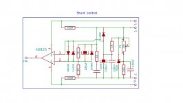
I keep hearing how good the Super Regulator is from the store, I never looked at it as I prefer shunts; using the sense wires gave me an idea for a super shunt regulator, spent a while thinking about it, I sketched out a 'Wien Bridge' circuit, ordered some parts, then mulled it over some more; the modded 'mini' shunt I use is from the TL431 datasheet, it already is an amplifier, and doing pretty much the same thing as the circuit I sketched - in that it has a dynamic control element, how much better would the new control circuit be, or would it?
While I'm waiting for parts, I'm looking for a simple(ish) circuit (that is easily audibly influenced by the PSU) that I can use to audition the shunts - my hearing is getting old lol.
Any recommendations?
While I'm waiting for parts, I'm looking for a simple(ish) circuit (that is easily audibly influenced by the PSU) that I can use to audition the shunts - my hearing is getting old lol.
Any recommendations?
While I'm waiting for parts, I'm looking for a simple(ish) circuit (that is easily audibly influenced by the PSU) that I can use to audition the shunts - my hearing is getting old lol.
Any recommendations?
IME it doesn't make any difference. Despite engineering dogma, opamp-based preamps are just as sensitive to ps quality as zero feedback, single ended valve stages with ultralow psrr.
Recently i ended up preferring a circuit similar to your super reg in comparison to a Salas BiB in an opamp phono stage. Liked it even better when each opamp had its own dedicated super reg.
Unfortunately, most shunt regulator designs require that there be very little or NO capacitance between regulated Vout and ground. So if you build a shunt regulator for a preamp and somebody tries to do "opamp rolling" on the preamp, using discrete opamps with bypass capacitors: kaboom! Instability. In fact many SMD-to-DIP8 adapters include bypass capacitance too, so good luck rolling in the latest and greatest opamps which are sold ONLY in SOIC-8 surfact mount packages.


I'm going to be unpopular , and suggest that actually the architecture - shunt or series - for regs really.does.not matter, because they do exactly the same thing: actively manage one 'arm' of the supply - the series , or the parallel.
- Shunt regs are sometimes justified on the spurious idea that that can deal with reactive current, that series regs cannot. This is simply untrue, for at least two reasons.
- Either approach is, for best performance, acutely sensitive to implementation.
My point being - whichever route you choose - to get the best out of it, you have to properly understand what you want to achieve, and how to measure that you've achieved what you sought.
tl;dr: Don't get seduced by the idea that a difference in the reg architecture, is rewarded by a somehow-fundamental difference (cough, 'improvement') in the response of the target supplied circuit: it is not.
Last edited:
Martin, you neglected to mention that the shunt regulator "architecture" (ugh) guarantees oscilloscope-viewable, repeatable, never-changing, constant ripple at the input to the regulator. In particular, the ripple does not change when the load current changes. The shunt removes one entire category of uncertainty.
The implementer can, of course, reduce this ripple as low as s/he likes, by filtering or other means. And with a constant current load thanks to the shunt "architecture" (ugh), reducing ripple becomes a little easier. Good old John Curl chooses to build a two stage circuit, using an LM317 IC voltage regulator to reduce ripple by 62 dB (@ 120 Hz), followed by a shunt regulator to deliver smooth output to the load. Of course this costs money ($0.58 qty 100), and board space, and voltage headroom to keep the first stage from Dropout. However, some designers conclude that the benefits outweigh the costs.
It's rather an elegant idea: a constant voltage circuit (LM317) drives the best possible load, namely a constant current source (shunt regulator).
~
Last edited:
Mark - that is very true: and for very low current draw loads, indeed elegant. But for much else - just wasteful.
But my real point was simply that, beyond a certain point of 'good enough', pursuing a 'better psu' for a given circuit element becomes essentially a neurotic activity, eeffort that might be better spent on more-carefully considering bypassing, control of loop areas, eradicating shared impedances - all that other good, really important stuff.
But my real point was simply that, beyond a certain point of 'good enough', pursuing a 'better psu' for a given circuit element becomes essentially a neurotic activity, eeffort that might be better spent on more-carefully considering bypassing, control of loop areas, eradicating shared impedances - all that other good, really important stuff.
Last edited:
In my line level designs there is no "waste" since I prefer to use 50 VA Rcore power transformers anyway. Choosing one with 4VAC greater secondary voltage (to account for the drop across the first regulator stage) adds zero extra cost, since 50VA is way more than I need, no matter how it's divvied up. 2x24VAC @ 1 amp is just as good as 2x20VAC @ 1.2 amps to me, since I'm only drawing 0.05 amps, and they cost the same.
The extra 4-5 dollars worth of parts cost isn't "waste" in my DIY projects, because purchasing and using them adds so much more fun and personal enjoyment to the enterprise. I don't even mind buying those black anodized PCB-mount heatsinks to prolong the lifetime and reliability of the shunt regulators. But naturally other designers may feel differently than I do.
The extra 4-5 dollars worth of parts cost isn't "waste" in my DIY projects, because purchasing and using them adds so much more fun and personal enjoyment to the enterprise. I don't even mind buying those black anodized PCB-mount heatsinks to prolong the lifetime and reliability of the shunt regulators. But naturally other designers may feel differently than I do.
That and optimal transformer snubbing (Quasimodo) will further remove uncertainties (or is snubbing assumed).Martin, you neglected to mention that the shunt regulator "architecture" (ugh) guarantees oscilloscope-viewable, repeatable, never-changing, constant ripple at the input to the regulator. In particular, the ripple does not change when the load current changes. The shunt removes one entire category of uncertainty.
Dan.
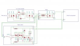
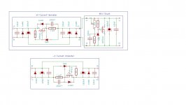
I use separate left and right power supplies. Each channel uses 80 watt R core TX, Mark’s CRC snubbers, 2 separate plus /minus soft recovery discrete diode bridges, 4 x 15,000 uf and 4 mh chokes as the CLC filter, Jung super regulator as preregulators for each phase, then Borbely jfet shunt regulator. Then I have no room for whatever I was going to power with it. The shunts and the line level circuit are in a separate chassis. Load draws 300 ma per channel at +\- 24 VDC
Attachments
Last edited:
It's rather an elegant idea: a constant voltage circuit (LM317) drives the best possible load, namely a constant current source (shunt regulator).
~
Use a DN2540 depletion mosfet PLUS LM317 and the PSRR will improve by 20dB at least.
Hello,
I find it interesting that some regulators provide information about impedance vs frequency. At least the super regs seem to focus on that. Would you think that it could affect performance significantly?
To be honest - and if the above makes sense - my real question is if a regulator with better specs is placed after an "inferior" one could it restore the bandwidth?
 What did you have before and how different does is sound?
- Status
- This old topic is closed. If you want to reopen this topic, contact a moderator using the "Report Post" button.
- Home
- Amplifiers
- Power Supplies
- Shunt reg shoot out