I'm trying to get 6.3VDC from a 6.3V winding. Current draw is 3.2A, the power transformer has a higher rating, so far so good.
I use a standard bridge cell and a 680 µF cap (advice from my parts salesman). Voltage drop on the rectifier is (supposed to be) 1V.
I put in the tubes (four 6N6P) and measure 5.8V! Sometimes I reach 5.9V but that's it.
I expected around 7-8V, what is going wrong? What am I missing?
The cap seemed way too small so I added 20.000 µF but that didn't change much.
Thanks in advance, kind regards.
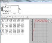
At this high current of 3.2A, this is quite challenging. In theory, the rectified voltage may reach 6.3V * sqrt(2), so around 8.8V. In pratice, this voltage is reduced by two times diode forward voltage, wiring resistance of the transformer and current draw vs. capacitance after rectifier.
By increasing the capacitor, the charge current into this capacitor will result in very high peaks. Therefore, you would need a much higher rated transformer to keep the internal resistance low and reduce the voltage drop. Also, using high current schottky diodes may help (e.g., MUR1010). Please also make sure the current ripple of the capacitor is within spec of datasheet. High ESR of the capacitor may also lead to lower charging voltage.
Finally, make sure your measurement equipment is able to measure this voltage. As there is still a high ripple voltage on the capacitor, this may lead to a faulty measurement.
You may simulate this small circuit in LTspice for validation.
It should be doable, but the AC current rating of the transformer needs to be ~twice the targeted DC output current.
You then have to use large enough schottky rectifiers (>10A) and a sufficient filter cap, at least 10000µF.
If it is not sufficient, there is still a last resort option: a synchronous rectifier.
I have described one or two examples using commodity parts
You then have to use large enough schottky rectifiers (>10A) and a sufficient filter cap, at least 10000µF.
If it is not sufficient, there is still a last resort option: a synchronous rectifier.
I have described one or two examples using commodity parts
A power factor of 0.5 (that's what we are discussing) is not cast in bronze, and the average value is in fact closer to 0.6 (but there are exceptions in both directions), but when you demand a lot from a winding, it is prudent to adopt 0.5 or less, even if the actual rms current is not going to reach these values, because otherwise you may miss your voltage target: you are already trying to scrape tenths of volt here and there.
AC filaments have been in use for decades, even for sensitive situations and with some care and attention, you should be able to make it work.
If it really doesn't, you will always have your "cheat" option open
AC filaments have been in use for decades, even for sensitive situations and with some care and attention, you should be able to make it work.
If it really doesn't, you will always have your "cheat" option open
Last edited:
Or feed DC just to the first tube filament, which is the most critical, and AC to the others.
This will simplify your requirements.
Makes no difference here: they are all parallel

But thanks for the tip!
- Status
- This old topic is closed. If you want to reopen this topic, contact a moderator using the "Report Post" button.
- Home
- Amplifiers
- Power Supplies
- 6.3 VDC from 6.3VAC winding? Output too low?