This is a bit of a shot in the dark, but apart from a few minutes of my time, i figure i've got nothing to lose.
2-transistor Black Regulator
A while ago, i took the liberty to tinker with the component values both in LTspice as well as the real-life circuit, and it works well enough for some of my applications.
Recently though, i "finally" decided to overhaul the power electronics in my active studio monitors. I particularly wasn't overjoyed with the heavy-handed way the powering of the line-level stages was done (series dropper resistors and a 78/7915 combo, supplied from the +/-40v feeding the power amps), since the thing ends up running a bit (or actually, MUCH) more "toasty" than i'd like.
So i decided to start in LTspice, and basically "mirror" the two-transistor regulator, to make it a negative buck (by, of course, flipping the polarities of all the silicon parts). Trouble is, though, that despite it working promisingly fine in theory / in simulation, the real-world circuit seems to disagree.
I got my hands on some BCP53-16 and BCP56-16 to use as pass-transistors (to give some extra wiggle-room power-wise, at least).
Either way, the negative regulator still refuses to start oscillating, in real life (while it does so readily, in LTspice).
The positive one's steaming along just fine, with 70-75% efficiency.
I've tried multiple combinations of resistors between the two transistors, but to no avail. Even replaced the R7 with a 10k trimmer, went from end to end, and still nothing
At best, it stays in linear mode; at worst, with 30v input, the output ramps up to 25v or so, at which point i switched off the bench supply.
That pretty much confirms that old tech-proverb: amplifiers oscillate, and oscillators amplify...
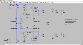
Attached you'll find a screenshot of the LTspice sim i've used, and the actual circuit uses the same components & values. If you might find the time to read through this, and perhaps throw an idea or two back, i'd dearly appreciate it, but otherwise, i'm somewhat stumped.
2-transistor Black Regulator
A while ago, i took the liberty to tinker with the component values both in LTspice as well as the real-life circuit, and it works well enough for some of my applications.
Recently though, i "finally" decided to overhaul the power electronics in my active studio monitors. I particularly wasn't overjoyed with the heavy-handed way the powering of the line-level stages was done (series dropper resistors and a 78/7915 combo, supplied from the +/-40v feeding the power amps), since the thing ends up running a bit (or actually, MUCH) more "toasty" than i'd like.
So i decided to start in LTspice, and basically "mirror" the two-transistor regulator, to make it a negative buck (by, of course, flipping the polarities of all the silicon parts). Trouble is, though, that despite it working promisingly fine in theory / in simulation, the real-world circuit seems to disagree.
I got my hands on some BCP53-16 and BCP56-16 to use as pass-transistors (to give some extra wiggle-room power-wise, at least).
Either way, the negative regulator still refuses to start oscillating, in real life (while it does so readily, in LTspice).
The positive one's steaming along just fine, with 70-75% efficiency.
I've tried multiple combinations of resistors between the two transistors, but to no avail. Even replaced the R7 with a 10k trimmer, went from end to end, and still nothing
At best, it stays in linear mode; at worst, with 30v input, the output ramps up to 25v or so, at which point i switched off the bench supply.
That pretty much confirms that old tech-proverb: amplifiers oscillate, and oscillators amplify...
Attached you'll find a screenshot of the LTspice sim i've used, and the actual circuit uses the same components & values. If you might find the time to read through this, and perhaps throw an idea or two back, i'd dearly appreciate it, but otherwise, i'm somewhat stumped.
the negative regulator still refuses to start oscillating.
Have you tried a load resistor (50R-100R) at the output?

I recently wanted to do just the same thing as the usual dropper resistor + zener gets annoying. It does not bode well that you couldn't... Have you succeeded after all?
It seems R2, R3, R5 and R7 are too small, they dissipate almost 1/2 W. If the current in the collector of Q2 or Q1 is too big, then it might not stabilize, especially if the load is too low. Are all transistor still working? Have you played around with the hysteresis cap C4? Is the core the same for L1 and L2? All those slight differences, together with the minor difference of behavior between NPN and PNP might explain your observations.
I was planning to add a "capacitor multiplier" with a transistor to smooth out the ripple on the bus. Did you find that additional filtering was required to operate opamps from this regulator?
Regards,
Geoffroy
- Status
- This old topic is closed. If you want to reopen this topic, contact a moderator using the "Report Post" button.