Hi Vishalk,
I'd say you could continue. If you use the lcrc configuration, check if it gives the expected rail voltage of +/- 18v approximately. If so it would seem everything works as expected with choke input supply.
The clcrc is also an option. it wil give higher rail voltages near +/- 29 volts. This is a very good power supply as well. You can vary with the resistor value to get to the desired rail voltage. 24V would be my preference. But whatch at the dissipation of those resistors (use psu designer and then calc out the dissipation, u=i*r and p=u*i)
In both cases try to stay under 30V rails voltage. Yet again i would advice to start with a test psu. with the caps you have ordered already it should be relatively easy to make such a supply. Some cement wirewound blocks are dirt cheap and will do for that. get some of those rectifier blocks and it would probably set you back some 25€
greetz,
Joris
Clearly you can appreciate an Hiraga amp with a choke input supply and I respect that.pieter t said:Sorry guys..
My own bass amp is Hiraga, with my version of a choke input supply and I am very happy with it.
Hello ,
You could make a CLEAR drawing of how you wanna use the Lundahl choke and ask Lundahl company. I remember i asked them too but some of my emails have been deleted.
You could try creating a load similar to the Hiraga amp and see how much dc output you will get. Like i said before voltage drop across the choke will be big when used in choke input. It is not V =I*R
Greetings, Ed
If you do not have measurement equipment to precisely measure & calculate the snubber capacitor/resistor network an advice given in Linear Audio (linearaudio.net) was to use 1kohm in series with 1 nF capacitor placed across the transformer windings just before the rectifier diodes. This combination would work in most any case and not cause issues.
Jesper
You need at least 10 nF, with bigger parts and more leakage inductance
a value of 100nF - 1uF is needed.
Do the math yourself:
You have only 32 Volt peak voltage. At 4 Ohm load peak current is 8 Ampere.
In the worst case the supply caps have to provide 8 Ampere for a duration of 1/100 Hz (8 ms realistically).
You need max of 50 mF on each supply rail (peak_current * 8 ms / ripple_voltage).
For ripple voltage a good value is 3 - 10% of the supply rails.
More caps are not only a waste of money, but are bad as they increase losses in the transformer due to vey high peak current pulses.
But of course they look impressive")
With your rather low supply every volt is important!
Therefore i would not recommend CLC filtering.
Use a circuit with good power supply ripple rejection instead.
You have only 32 Volt peak voltage. At 4 Ohm load peak current is 8 Ampere.
In the worst case the supply caps have to provide 8 Ampere for a duration of 1/100 Hz (8 ms realistically).
You need max of 50 mF on each supply rail (peak_current * 8 ms / ripple_voltage).
For ripple voltage a good value is 3 - 10% of the supply rails.
More caps are not only a waste of money, but are bad as they increase losses in the transformer due to vey high peak current pulses.
But of course they look impressive
With your rather low supply every volt is important!
Therefore i would not recommend CLC filtering.
Use a circuit with good power supply ripple rejection instead.

Hello,
Rectifiers arrived, lovely kit actually. Comes with everything in the box!
So NOW you can check how much dc output your supply will deliver with a bias current of about 1,5A using the LL2733 for choke input. It will probably be around 20 volts. If it is on the lower side you could choose a lower bias current.
With tube gear sometimes when the dc voltage is a bit to low they will add a small cap between the rectifier and the choke making it a CLC BUT if the first is low enough in value it will work like a choke input but with a higher dc output.
But first tell us what dc you are getting.
greetings, eduard
Your parts look very good, maybe a bit expensive
I did some reading and thinking,
and now understand the problems with the power supply
and the Hiraga amp better.
The Hiraga Amp is in principle a low cost amp.
A simple circuit with a handful transistors,
nothing special.
Matching between PNP and NPN is bad,
therefore a offset trimmer is mandatory.
The open loop gain is about 150, the
closed loop gain is about 20.
Therefore distortion (THD) is bad by today standards.
Frequency response is very good without overshoot
and ringing up to 100 kHz.
A big problem is the missing short circuit protection
and the very bad clipping behaviour!
15 Ampere and more are flowing from the NPN to
the PNP power transistor in case of clipping...
The second big problem is the poor power supply
ripple rejection.
The solution is a supply with very low ripple.
How to get this?
First the brute force: Use really huge caps as often seen
Second, think somewhat: Use a C-R-C or C-L-C filter
Third, think more: Use a regulated supply.
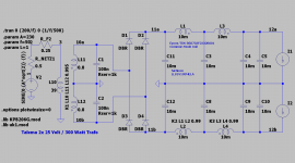
A good and relativly cheap alternative C-L-C supply is in the attached picture:
It uses a Talema toroidal transformer with 300 Watt and 2 x 25 Volt
output (Euro 55 at Farnell).
It does not make much sense to use separate transformers for
each side, if they are in the same housing.
Channel separation is not very important in stereo, about 20-30 dB
is more than sufficient and this is easily to achive.
The positive and negative supply is filtered by 4 x 10 mF
Nichicon LLS1V103MELA caps (Euro 2.9 @ Mouser).
For a tight budget, 3x 10 mF or 3 x 4.7 mF are OK too.
Two Epcos common mode chokes B82733F2232B001 are used
to filter the ripple (Euro 2.4 at Mouser) down to less than a millivolt!
The Epcos have about 0.15 Ohm series resistance and therefore
do not cost much headroom.
Be careful to insert them correctly so that the 100 Hz ripple
is seen as common mode.
The rectifier is a GBU806 or similar (1 Euro @Mouser).
A RC snubber (100nF + 1kOhm) over each secondary winding
damps oscillations due to parasitic inductance of the
transformator. A secondary 100 nF should be used
directly at each amplifier.
At the primary side a 1.5 Amp / 250 Volt glas fuse is used (
Bel 5TT 1.5-R or similar, 0.3 Euro @Mouser)
To be on the safe side, each channel should have a
separate 3 Ampere fast fuse, especially as the
Amp has no electronic current limiter!
Total part costs are about 90 Euros for the supply.
I think, that from a technical point of view this is a good
starting point for the Hiraga class-A amp.
Edit: The attached picture was wrong...
Greetings,
Udo
I did some reading and thinking,
and now understand the problems with the power supply
and the Hiraga amp better.
The Hiraga Amp is in principle a low cost amp.
A simple circuit with a handful transistors,
nothing special.
Matching between PNP and NPN is bad,
therefore a offset trimmer is mandatory.
The open loop gain is about 150, the
closed loop gain is about 20.
Therefore distortion (THD) is bad by today standards.
Frequency response is very good without overshoot
and ringing up to 100 kHz.
A big problem is the missing short circuit protection
and the very bad clipping behaviour!
15 Ampere and more are flowing from the NPN to
the PNP power transistor in case of clipping...
The second big problem is the poor power supply
ripple rejection.
The solution is a supply with very low ripple.
How to get this?
First the brute force: Use really huge caps as often seen
Second, think somewhat: Use a C-R-C or C-L-C filter
Third, think more: Use a regulated supply.
A good and relativly cheap alternative C-L-C supply is in the attached picture:
It uses a Talema toroidal transformer with 300 Watt and 2 x 25 Volt
output (Euro 55 at Farnell).
It does not make much sense to use separate transformers for
each side, if they are in the same housing.
Channel separation is not very important in stereo, about 20-30 dB
is more than sufficient and this is easily to achive.
The positive and negative supply is filtered by 4 x 10 mF
Nichicon LLS1V103MELA caps (Euro 2.9 @ Mouser).
For a tight budget, 3x 10 mF or 3 x 4.7 mF are OK too.
Two Epcos common mode chokes B82733F2232B001 are used
to filter the ripple (Euro 2.4 at Mouser) down to less than a millivolt!
The Epcos have about 0.15 Ohm series resistance and therefore
do not cost much headroom.
Be careful to insert them correctly so that the 100 Hz ripple
is seen as common mode.
The rectifier is a GBU806 or similar (1 Euro @Mouser).
A RC snubber (100nF + 1kOhm) over each secondary winding
damps oscillations due to parasitic inductance of the
transformator. A secondary 100 nF should be used
directly at each amplifier.
At the primary side a 1.5 Amp / 250 Volt glas fuse is used (
Bel 5TT 1.5-R or similar, 0.3 Euro @Mouser)
To be on the safe side, each channel should have a
separate 3 Ampere fast fuse, especially as the
Amp has no electronic current limiter!
Total part costs are about 90 Euros for the supply.
I think, that from a technical point of view this is a good
starting point for the Hiraga class-A amp.
Edit: The attached picture was wrong...
Greetings,
Udo
Attachments
Last edited:
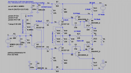
There is another nice trick to increase the power supply rejection
of the Hiraga Amp:
A high value resistor (R23 in the picture) in series with a 100nF
is used to inject some ripple at the input in a way
that the ripple at the output is cancelled.
This works very good in simulation and is worth a trial.
It depends on the matching of the transistors if the Resistor should
point to the V+ or the V- supply. In simulation a value of about 8.3 Megaohm
is right, but this needs experimentation.
In addition the various resistors are changed to get somewhat
better performance (lower input bias currents and higher predriver and driver
currents) and to set the output quiescent current to 2 Ampere.
By using 15 Volt Zener diodes, the amp works with a higher range of supply values
(18 volts up to 35 volts are OK).
The predriver current is send directly to the output to do some useful work
instead of getting wasted.
The gain is set to 20, about 1 Vrms is needed for full output.
EDIT: Forget to mention the Talema part number in the last post: RS0300P1-2-025
And note that the first Epcos common mode coil is used for L1 and L2,
and the second is used for L3 and L4
Attachments
Last edited:
Udok I appreciate the information and the thought that went into it, this would make for another good project for the Hiraga, you should give it a go! Be part of the Hiraga group of owners and diy'ers.
Now the thing is I have to work with what I have! That's the challenge I'm faced with, I just want to build a PSU with chokes but know how, why, the values to use, what to measure and check for etc.
Now the thing is I have to work with what I have! That's the challenge I'm faced with, I just want to build a PSU with chokes but know how, why, the values to use, what to measure and check for etc.
Hi Vishalk,
Clear, you want to use the parts you have. so these are the options you have as far as I can see:
1) Lcrcc psu.
You will have to buy two more Lundahl chokes but you can use the caps trannies and rectifiers you have. Substitute the resistors for the common mode chokes Udok mentioned if you want. T use one Lundahl per rail, parallel connected.
2) clcrc psu.
You can use the lundahls you have in common mode choke. Whatch the dissipation at those resistors (the formula's i gave where meant for the resistor not the coils. They are correct for the resistor's. Eduard misunderstood me there i assume). Don't use resistors above 50% of their dissipation rating for reliability and longevity.
Disclaimer: I have not checked the datasheets for the rectifiers regarding charge currents or simulated them.
3) r bridge r clcrcc
This option places some series resistors before and after the rectifier bridge. Something like ,1R would do. This wil limit the charging currents in the first cap a bit. It simulates the slow and soft turn of characteristic of a tube rectifier. You will loose a large part of the pro's for those nice rectifiers though.
Consider option one and two. Aim at rail voltages between 24 and 28 V. As pointed out by both me and Pieter higher voltages and currents will decrease the life expectance of the output transistors if not instant failure. As a general guideline something like 25 to 30 watts per power device is advisable as a maximum for continuous dissipation.
For testing: Buy four 36R/25W power resistors. connect two of these in parallel and clamp them to the heatsinks. Then connect them to the output of the psu. One per rail and one channel at a time.
The resistors will simulate the load of the actual amp. about the same current draw. this way you can measure voltages before connecting the actual amp circuit.
Do a search about initial testing and startup. It will give good advice, the light bulb procedure is good. You said you still have construction wiring in store. use it for initial building and testing. Don't start with solid copper bars and such untill you have that figured out.
When you have decided what you are going to do let us know. I will adapt the schematic posted to your choice with a more complete layout, parts and values. This keeping with what you have already.
grtz
Joris
ps for sound quality I would opt for option one. This WILL be the best sounding. Given that is seems you want to max out this build, buy the extra Lundahls. Alternatively start with option two and save money for option one. rewiring is not that difficult.
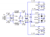
This is a supply I have used with my Hiraga. The channels are isolated – left outputs, input section, right outputs.
The chokes are followed by capacitors without a ground connection as this gives me 20,000uf instead of 5,000uF for the two cans, and the ground connection isn’t going to be doing much at this point. This deals with the majority of the differential mode ripple. The small chokes and small stacked capacitors following deal with common mode noise.
This is the capacitor input version which I used to increase the Voltage for the transformer I was using, and had the schematic for. The grounds go back to a single point.
Attachments
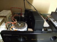
This is a picture of the chokes I use, with my old JLH amplifier. They are lighting ballasts, have an inductance of 95mH and a DCR of around 0.1 ohms if I remember correctly. This is more inductance than I need for the choke input version and they handle the DC well even though they are not gapped. They weigh around 14Kg each, and this is good because they have proved suitable through several different versions of supply and different amps. The low resistance is recommended for a higher current amp.
Attachments
- Home
- Amplifiers
- Power Supplies
- 30w Jean Hiraga Power Supply Design, one large capacitor or several?