Surely the amount of amps you measure will be determined by the load resistors you use, so I’m confused what this tells you. Seems like circular logic to me...
Yup just making sure and actually learning as i go along!
Hi,
In reply to the pm i scanned the thread quickly. Good info and advise from Alan. At first glance everything checks out ok and approximately as simmed and calculated. nice")
I would still like to see a voltage measurement for each rail voltage at the same time. That would require two Multimeters (MM). I don't know if the multimeter is an rms one. If it is, i would try and measure ac across both rails as well. should be near zero. for clarity, connect the positive rail mm between positive output to the red mm lead (+28v) and the black lead to central ground. reverse for negative rail (red to -28v, black to central grround) even the cheapest mm's will do for the dc voltage. Voltage differential should be about the same (+28V/-28V).
If all checks out you can start building. don't worry about the 2r2 resistors. I specified 2*3w and you used 2*7w. Yes they get hot but they are well within rating, no more then 30% guestimate. These are rated in free air. push them apart a bit for allowing more air flow around them. They will be ok for now anyway, get it working and listen to the amp before changing anything now.
I will be out for holidays two weeks from saturday, so wont be much help during that time. However, if the measurements all check out, i'd suggest moving over to the thread in the solid state forum. Go there for help in getting the amp circuits working. I will check when i can but pm with a link is ok too.
regards,
Joris
In reply to the pm i scanned the thread quickly. Good info and advise from Alan. At first glance everything checks out ok and approximately as simmed and calculated. nice
I would still like to see a voltage measurement for each rail voltage at the same time. That would require two Multimeters (MM). I don't know if the multimeter is an rms one. If it is, i would try and measure ac across both rails as well. should be near zero. for clarity, connect the positive rail mm between positive output to the red mm lead (+28v) and the black lead to central ground. reverse for negative rail (red to -28v, black to central grround) even the cheapest mm's will do for the dc voltage. Voltage differential should be about the same (+28V/-28V).
If all checks out you can start building. don't worry about the 2r2 resistors. I specified 2*3w and you used 2*7w. Yes they get hot but they are well within rating, no more then 30% guestimate. These are rated in free air. push them apart a bit for allowing more air flow around them. They will be ok for now anyway, get it working and listen to the amp before changing anything now.
I will be out for holidays two weeks from saturday, so wont be much help during that time. However, if the measurements all check out, i'd suggest moving over to the thread in the solid state forum. Go there for help in getting the amp circuits working. I will check when i can but pm with a link is ok too.
regards,
Joris
Last edited:
Thanks Joris!
I have two multimeters and the voltages were the same, i also did a check for AC voltages and it was near 0! Thanks to you i have got this far (and other members) but you helped greatly by designing the PSU.
Ok lets finish building this! Let me know when you are back from Holidays. Enjoy!
I have two multimeters and the voltages were the same, i also did a check for AC voltages and it was near 0! Thanks to you i have got this far (and other members) but you helped greatly by designing the PSU.
Ok lets finish building this! Let me know when you are back from Holidays. Enjoy!
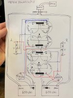
Hi, I build my Hiraga with pcb from Jims Audio 4 years ago.
Build PSU from drawings from diyaudioprosject.com with some different values.
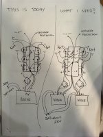
But I have missunderstand it all, drawings show just one canal.
I use PSU for one canal for bouth Left and Right ) :
Here is some drawings and picture.
What do you people think of this?
It plays good, stabile +- 30mv dc on output, some hum from speaker within 1m but no problem when playing music.
Frank
Build PSU from drawings from diyaudioprosject.com with some different values.
But I have missunderstand it all, drawings show just one canal.
I use PSU for one canal for bouth Left and Right ) :
Here is some drawings and picture.
What do you people think of this?
It plays good, stabile +- 30mv dc on output, some hum from speaker within 1m but no problem when playing music.
Frank
Attachments
Hello,Your parts look very good, maybe a bit expensive
I did some reading and thinking,
and now understand the problems with the power supply
and the Hiraga amp better.
The Hiraga Amp is in principle a low cost amp.
A simple circuit with a handful transistors,
nothing special.
Matching between PNP and NPN is bad,
therefore a offset trimmer is mandatory.
The open loop gain is about 150, the
closed loop gain is about 20.
Therefore distortion (THD) is bad by today standards.
Frequency response is very good without overshoot
and ringing up to 100 kHz.
A big problem is the missing short circuit protection
and the very bad clipping behaviour!
15 Ampere and more are flowing from the NPN to
the PNP power transistor in case of clipping...
The second big problem is the poor power supply
ripple rejection.
The solution is a supply with very low ripple.
How to get this?
First the brute force: Use really huge caps as often seen
Second, think somewhat: Use a C-R-C or C-L-C filter
Third, think more: Use a regulated supply.
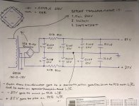
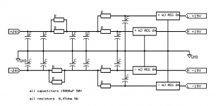
A good and relativly cheap alternative C-L-C supply is in the attached picture:
It uses a Talema toroidal transformer with 300 Watt and 2 x 25 Volt
output (Euro 55 at Farnell).
It does not make much sense to use separate transformers for
each side, if they are in the same housing.
Channel separation is not very important in stereo, about 20-30 dB
is more than sufficient and this is easily to achive.
The positive and negative supply is filtered by 4 x 10 mF
Nichicon LLS1V103MELA caps (Euro 2.9 @ Mouser).
For a tight budget, 3x 10 mF or 3 x 4.7 mF are OK too.
Two Epcos common mode chokes B82733F2232B001 are used
to filter the ripple (Euro 2.4 at Mouser) down to less than a millivolt!
The Epcos have about 0.15 Ohm series resistance and therefore
do not cost much headroom.
Be careful to insert them correctly so that the 100 Hz ripple
is seen as common mode.
The rectifier is a GBU806 or similar (1 Euro @Mouser).
A RC snubber (100nF + 1kOhm) over each secondary winding
damps oscillations due to parasitic inductance of the
transformator. A secondary 100 nF should be used
directly at each amplifier.
At the primary side a 1.5 Amp / 250 Volt glas fuse is used (
Bel 5TT 1.5-R or similar, 0.3 Euro @Mouser)
To be on the safe side, each channel should have a
separate 3 Ampere fast fuse, especially as the
Amp has no electronic current limiter!
Total part costs are about 90 Euros for the supply.
I think, that from a technical point of view this is a good
starting point for the Hiraga class-A amp.
Edit: The attached picture was wrong...
Greetings,
Udo
As i understoodd, i am good to go with just one of this transfomer to connect on two Power Supply as you described. One Power Supply per Hiraga PCB Channel. Is it ok?
You can use one transformer if the power rating is Ok for your needs.
You can even use one transformer and only one power supply circuit (cap + filter) and connect the left and right Hiraga channels to it.
Many amplifiers do it this way to save cost and space and audio quality will not suffer.
Regards,
Udo
You can even use one transformer and only one power supply circuit (cap + filter) and connect the left and right Hiraga channels to it.
Many amplifiers do it this way to save cost and space and audio quality will not suffer.
Regards,
Udo
Thanks so much! I dont want so much power rating. It will save cost and space, of course. I think just one 300VA toroidal transformer is ok for my needs.You can use one transformer if the power rating is Ok for your needs.
You can even use one transformer and only one power supply circuit (cap + filter) and connect the left and right Hiraga channels to it.
Many amplifiers do it this way to save cost and space and audio quality will not suffer.
Regards,
Udo
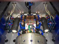
Great improvement, it looks like a massive power supply! Please, where did you buy those caps and big resistors? May you share the schematics?Regards! I am just begging my Hiraga project and choosing the best way.Hi, here is my Hiraga today. 2 transformers and 8+100000uf caps. Compare with old version, 4 posts back.
View attachment 1010332 View attachment 1010333
By the way, does it sound beeter with dual power supply? Just let me know when you have the draw. Regards!Hi, the caps is from hificollectiv ( F&T G Radial Cap ). But out of stock now. The resistor I got from ebay ( Dale ).
I dont have a schematic for the amp, but I can draw one. Give me some time ( :
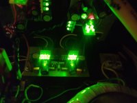
I have been using regulators with classic filtration in the power supply of Class A amplifiers for the last 5 years. The regulators are well known Improved_PN_Regs by Walt Jung but improved and modified for higher currents, they are tested on 5A. The minimum voltage drop across them is 3V. I first used them in JLH2003 then Le monstre and now in Hiraga 20W A class (picture below). I am very pleased with the results as well as the sound so they stay in the amp forever.
Attachments
- Home
- Amplifiers
- Power Supplies
- 30w Jean Hiraga Power Supply Design, one large capacitor or several?