Howdy everyone!
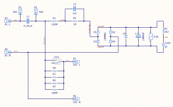
I discovered this diyAudio Soft Start build guide (PDF), and upon reading it was blown away with how clear, intuitive and brilliantly explained it was. Thanks @JojoD818!
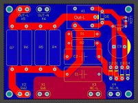
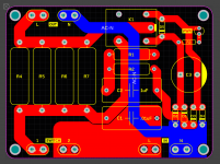
In the interests of learning, I put together a new PCB based on the schematic and general component layout provided, however I wanted the output headers to be on the opposite side of the board to the input and switch headers. As such, I've moved components around to accommodate, as well as having the luxury of a 2-layer board (I'll be getting PCBs produced).
Given that this involves mains wiring, I figure it can't hurt to have some input over the layout and design, with a couple of notes:
1. The bottom (blue) ground pour is entirely the AC Neutral net.
2. There is one pour on the top (red layer), connecting the AC Live terminal to the one side of the switch. The rest of traces run along the top, minimum 100mil for the most part, but 200mil where possible.
3. Is @JojoD818's overall design in the PDF still considered robust - i.e. a great, simple execution of a soft start circuit, or has there been any collective improvement to conventional wisdom in the intervening years?
4. The power supply this will connect to will feature a couple of 400VA transformers, with about 25000uF each, driving a stereo 8xLM3886 amplifier.
Thanks - any and all feedback welcome!
I discovered this diyAudio Soft Start build guide (PDF), and upon reading it was blown away with how clear, intuitive and brilliantly explained it was. Thanks @JojoD818!
In the interests of learning, I put together a new PCB based on the schematic and general component layout provided, however I wanted the output headers to be on the opposite side of the board to the input and switch headers. As such, I've moved components around to accommodate, as well as having the luxury of a 2-layer board (I'll be getting PCBs produced).
Given that this involves mains wiring, I figure it can't hurt to have some input over the layout and design, with a couple of notes:
1. The bottom (blue) ground pour is entirely the AC Neutral net.
2. There is one pour on the top (red layer), connecting the AC Live terminal to the one side of the switch. The rest of traces run along the top, minimum 100mil for the most part, but 200mil where possible.
3. Is @JojoD818's overall design in the PDF still considered robust - i.e. a great, simple execution of a soft start circuit, or has there been any collective improvement to conventional wisdom in the intervening years?
4. The power supply this will connect to will feature a couple of 400VA transformers, with about 25000uF each, driving a stereo 8xLM3886 amplifier.
Thanks - any and all feedback welcome!
Attachments
Probably not good to use a plane for the neutral as there is no guaranty L and N are not switched at the mains outlet.
Hi Mark - thanks for the reply! Aha, okay - so if it was switched, that would mean Live would be on the pour - why exactly would that be a problem?
Creepage!!!
JP
Hi @JPS64 - care to elaborate?

[EDIT]
Okay, wowza. That little word was all I needed to know. Creepage. Gotcha! Killing the ground plane in favour of traces that steer well clear of the pads connected to Live. Thanks!
Last edited:
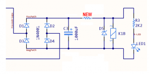
I recommend you add a new resistor to the circuit. Its purpose is to limit the worst case maximum current flowing in zener diode D5, if you've accidentally sized capacitor C2 too large; or if you've accidentally underestimated the relay coil's resistance; or if the AC mains voltage unexpectedly rises to the top end of its tolerance band.
I suggest you choose its resistance so that, at nominal mains AC voltage, the current in D5 is about 1.0X the current in the relay coil (from the relay datasheet).
_
I suggest you choose its resistance so that, at nominal mains AC voltage, the current in D5 is about 1.0X the current in the relay coil (from the relay datasheet).
_
Attachments
I recommend you add a new resistor to the circuit. Its purpose is to limit the worst case maximum current flowing in zener diode D5, if you've accidentally sized capacitor C2 too large; or if you've accidentally underestimated the relay coil's resistance; or if the AC mains voltage unexpectedly rises to the top end of its tolerance band.
I suggest you choose its resistance so that, at nominal mains AC voltage, the current in D5 is about 1.0X the current in the relay coil (from the relay datasheet).
_
Great idea - thanks!
I chose a completely different approach and used a phase controlled triac soft start circuit. I used an 8 pin PIC micro to control the triac and monitor the mains.
When the mains comes on it slowly ramps up the phase angle.
If mains goes it resets until mains starts again.
With a pretty bog standard triac I could control up to 2000 watts amplifier.
The only downside was the heatsink needed for the triac.
When the mains comes on it slowly ramps up the phase angle.
If mains goes it resets until mains starts again.
With a pretty bog standard triac I could control up to 2000 watts amplifier.
The only downside was the heatsink needed for the triac.
An externally hosted image should be here but it was not working when we last tested it.
An externally hosted image should be here but it was not working when we last tested it.
Last edited:
i will use an isolator on the mains nevertheless. a double pole single throw toggle at least, this way, on power off, no chance of electric shocks downstream...
the relay contacts used will determine the robustness of your soft starter, the higher the current rating of contacts implied lower contact resistance...
the choice of relays will be determined by your trafo size and its dc resistances, then the total capacity of psu reservoir caps..
all these taken together will give you an idea how to proceed...
the soft starter is not an end by itself, it is just the beginning of a wonderful project...
have fun....
Updated PCB attached. Have yet to add the additional resistor as per Mark's suggestion.
Yeah, now that I'm a little more aware of creepage I've killed the pour in favour of a single, direct trace. The blue layer is AC Neutral. Does this look a little less deadly?
Hi ABZA, what is the advantage of the mains plane? Does it work as a shield like a ground plane does? Wouldnt it be better to keep the mains traces as short as possible with minimal loop area?
Yeah, now that I'm a little more aware of creepage I've killed the pour in favour of a single, direct trace. The blue layer is AC Neutral. Does this look a little less deadly?
Attachments
I have tried a few different setups in the past but since then I have settled on this one.
DIY ELECTRONICS PROJECTS: MAINS ON DELAY CIRCUIT (SOFT START)
DIY ELECTRONICS PROJECTS: MAINS ON DELAY CIRCUIT (SOFT START)
Updated PCB attached. Have yet to add the additional resistor as per Mark's suggestion.
Yeah, now that I'm a little more aware of creepage I've killed the pour in favour of a single, direct trace. The blue layer is AC Neutral. Does this look a little less deadly?
I am not sure you understood the clearance and creepage concepts in PCB design. JP gives you some hints but you need to do some serious reading on the subject. Just look at how close the mains carrying traces are to the mount holes on your PCB. There are other issues as well, e.g. names N and L are not guarantied to stand if someone, let say in Germany, turns the mains plug up side down. I would suggest to use "non-polarized" designation for the mains inputs and outputs and design your PCB such that it is immune to "hot" and "cold" leads swapping.
One thing you should always remember - if something happens to another person or a property of those who use your design because you did not follow safety regulations, you will be liable. This is probably one of the reasons why even experienced diyers on this forum stay away from publishing their mains powered circuits. I am sure many use them in their on setups but only few share them.
Regards,
Oleg
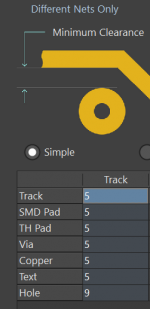
5mm between L and N.
9mm to earth.
On PCB and air.
JP
Thanks JP! Your earlier comment led me to a TI document where these were revealed to be the magic numbers. Will keep them in mind. Do these apply to both exposed pads as well as traces / internal layers?
I have tried a few different setups in the past but since then I have settled on this one.
DIY ELECTRONICS PROJECTS: MAINS ON DELAY CIRCUIT (SOFT START)
Baie dankie meneer! Will investigate this one
I am not sure you understood the clearance and creepage concepts in PCB design. JP gives you some hints but you need to do some serious reading on the subject.
Ha ha, couldn't agree more!
Just look at how close the mains carrying traces are to the mount holes on your PCB.
Aha, that makes sense. I assume it's best to treat the mounting holes as if they were earthed, in which case >9mm from the traces / pads is ideal?
I would suggest to use "non-polarized" designation for the mains inputs and outputs...
Also a great point, particularly as it relates to eliminating potential language barriers. Fortunately the design IS non-polar, so I've removed the "L" and "N" designators as in the original design doc.
One thing you should always remember - if something happens to another person or a property of those who use your design because you did not follow safety regulations, you will be liable. This is probably one of the reasons why even experienced diyers on this forum stay away from publishing their mains powered circuits. I am sure many use them in their on setups but only few share them.
Thanks for the words of caution! That is - of course - why I'm asking these questions now, rather than first burning down my house in a horrific LM3886-induced accident. I appreciate your input, and your patience at what must seem irritating/amateurish questions. I'm still learning
PCB FR4 is 10kV/mm so no problem between top or bottom routes (a lot of layouter use multilayer and the isolation ability of FR4 material)
Green Stop is generally 70V.
You can extend creepage on PCB between traces with milled slots but you don´t extend creepage on air.
What do you use for tool: is it possible to work with routinh constraints?
JP
Green Stop is generally 70V.
You can extend creepage on PCB between traces with milled slots but you don´t extend creepage on air.
What do you use for tool: is it possible to work with routinh constraints?
JP
PCB FR4 is 10kV/mm so no problem between top or bottom routes (a lot of layouter use multilayer and the isolation ability of FR4 material)
Awesome, that's good to keep in mind!
What do you use for tool: is it possible to work with routinh constraints?
I'm using Circuit Studio (or a very old version of Altium if needed) so I should be good for setting up routing clearances. Perhaps like the attached - 5mm trace distances, with 9mm to the holes (earth)?
Attachments
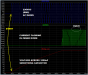
I recommend you add a new resistor to the circuit. Its purpose is to limit the worst case maximum current flowing in zener diode D5, if you've accidentally sized capacitor C2 too large; or if you've accidentally underestimated the relay coil's resistance; or if the AC mains voltage unexpectedly rises to the top end of its tolerance band.
I suggest you choose its resistance so that, at nominal mains AC voltage, the current in D5 is about 1.0X the current in the relay coil (from the relay datasheet).
_
R1 already does that to some extent.
R1 already does that [reduce the Zener diode current] to some extent.
Regrettably, not enough. With R1=220 as shown in the schematic, I'm seeing Zener currents over 70 milliamps, which will heat up the 24V Zener unnecessarily.
Adding the new resistor shown in post #6 will let you drop the zener current to whatever value you prefer; I have suggested 1.0X the relay coil current (16.7 mA). Not a bad improvement for $0.01 worth of extra components.
_
Attachments
Last edited:
- Status
- This old topic is closed. If you want to reopen this topic, contact a moderator using the "Report Post" button.
- Home
- Amplifiers
- Power Supplies
- Critique my Soft-Start PCB!