Adding the new resistor shown in post #6 will let you drop the zener current to whatever value you prefer; I have suggested 1.0X the relay coil current (16.7 mA). Not a bad improvement for $0.01 worth of extra components.
Wow, thanks for the detailed explanation!
Okay, at the risk of exposing my shocking mathematical abilities (or lack thereof), would the following calculation for that resistor be as follows?
Mains voltage: 230VAC
Relay coil current = 16.7mA / 1000 = 0.0167A
Current limiting resistor (R) = V/I = 230VAC / 0.0167A = ~13772R.
Closest resistor value: 13.5kOhm
(The simulator and) I just discovered a great advantage of the original circuit in post #1, which unfortunately disappears when you add the new resistor in post #6:If you add the new resistor shown in post #6, which I now do NOT recommend, the voltage across C3 rises sky high, requiring you to buy a much more expensive and physically much larger electrolytic cap. That's not an improvement, that's a downgrade! Oops!
Instead, I'd suggest simply using a 24V zener diode with a higher power rating. If its peak current is 75mA as simulation suggests, just use a 5W rated zener and be happy. The 1N5359 is one candidate; Mouser has twenty thousand of them in stock on the shelf (link). Be sure to use the appropriate PCB layout footprint, this diode is physically bigger than a typical 400mW zener.
I apologize for the mistake and the distraction!
And oh by the way, the dissipation in the LED's current limiting resistor R3 is awfully close to 1/4 watt (calculate it!), which might make you nervous if you plan to stuff a 250mW resistor in that position. So, you may want to either use a 1/2 watt resistor for R3, or else reduce the LED current somewhat. If you used an LED whose brightness was >5000 millicandelas, you could run it at only 2mA and it'd still be very very bright.
~
- Zener diode D5 clamps the voltage across large electrolytic capacitor C3, preventing it from ever rising above 24V.
Instead, I'd suggest simply using a 24V zener diode with a higher power rating. If its peak current is 75mA as simulation suggests, just use a 5W rated zener and be happy. The 1N5359 is one candidate; Mouser has twenty thousand of them in stock on the shelf (link). Be sure to use the appropriate PCB layout footprint, this diode is physically bigger than a typical 400mW zener.
I apologize for the mistake and the distraction!
And oh by the way, the dissipation in the LED's current limiting resistor R3 is awfully close to 1/4 watt (calculate it!), which might make you nervous if you plan to stuff a 250mW resistor in that position. So, you may want to either use a 1/2 watt resistor for R3, or else reduce the LED current somewhat. If you used an LED whose brightness was >5000 millicandelas, you could run it at only 2mA and it'd still be very very bright.
~
Last edited:
(The simulator and) I just discovered a great advantage of the original circuit in post #1, which unfortunately disappears when you add the new resistor in post #6...
...I apologize for the mistake and the distraction!
Not at all, I appreciate the brainpower, all in the name of learning!
And oh by the way, the dissipation in the LED's current limiting resistor R3 is awfully close to 1/4 watt (calculate it!), which might make you nervous if you plan to stuff a 250mW resistor in that position. So, you may want to either use a 1/2 watt resistor for R3, or else reduce the LED current somewhat.
This is one area I managed to think ahead - I already have a pile of 1/2W 2.2K resistors which will fit the bill here fine
Thanks for the heads-up.Question:
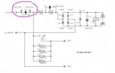
I understand a little about capacitive reactance, and that low-value caps impede the flow of current in an AC circuit.
As such, I figure the job of C11 in the soft-start schematic attached is there to restrict the current when the switch is off.
However, why is C11 there there at all? Why not simply let the switch to make or break the circuit, instead of allowing (even a small amount of) current to flow through C11 when it's off? Wouldn't it be safer to cut all power to the board when the switch is off, rather than allow a little current to trickle through C11?
Attachments
Question:
However, why is C11 there there at all? Why not simply let the switch to make or break the circuit, instead of allowing (even a small amount of) current to flow through C11 when it's off? Wouldn't it be safer to cut all power to the board when the switch is off, rather than allow a little current to trickle through C11?
The switch is there to soak up arcing from the switch contacts.
It also filters out switching noise to the amp.
- Status
- This old topic is closed. If you want to reopen this topic, contact a moderator using the "Report Post" button.
- Home
- Amplifiers
- Power Supplies
- Critique my Soft-Start PCB!