I Have modified an Ak4495 DAC and also the I/O board. This board controls usb/sdcard interface, lcd display, clock pulse for Dac, etc. The I/O board gets one secundary AC 9V/4A, which is a lot because the board only uses up to 1 A.
Now i have used the same 9V AC for a separate oscillator board, it has it’s own regulator board. Because things get warm inside the case, i want to attach a 5V/200mA fan with powerboard to the well known 9V AC.
An oscillator board, a sensitve I/O board fed by several Lm317 in pre-regulation mode and now a fan.
Do these 3 interfere with each other in a bad way, can i do something about it ?
There is no room for more transformers and if possible i want to skip external supply.
Attachments
Last edited:
Reusing the same AC input with another rectifier+filter (and a common ground somewhere else downstream) is a recipe for trouble.Now i have used the same 9V AC for a seperate oscillator board, it has it’s own regulator board.
What should be done is to use the same raw DC for different regulators, just after the filter cap, but the rectifier+cap need to be common to all the supplies (except when all the loads are floating, but that's exceptional).
Maybe, but only if you can accurately control the ground paths, which can be difficultCan I just remove the rectifier bridge on the separate board, but leave the capfilter intact ?
Dividing parts can be the best method, but only when properly applied, ie. completely divided and floating from the start: if you have circuits already connected somewhere upstream, joining them downstream with all the intervening noise of rectification in-between is generally going to cause problems, because you will create various noisy loops (I have already seen a number of threads on that subject). The one on the + rail is probably going to be handled smoothly by the regulator (but it will be an additional burden), but the ground loop cannot be eliminated that simply.What goes wrong ? I thought dividing parts all the way is the best method.
The best technique is to start from a good ground scheme for all of the loads, and build the rest around this skeleton.
In general, having a big central filter cap is going to be the simplest and most effective solution.
If you want to separate the circuits (which can be advisable if some of the loads are noisy), you best bet is to keep a good, low impedance ground system, either equipotential, or iterative, following the paths of key signals, or else, and separate the +rail circuits using some kind of series impedance + local bypassing at the point of load.
The kind of series impedance to be used depends on the current drawn by the load: with a high current draw, a pure resistance is going to dissipate too much, so a small inductance is the way to go, preferably damped by a small series resistance, either as a discrete resistor or as a winding resistance to damp any possible resonances, and if the current is small, up to tens of mA's, a suitable resistor is perfectly OK.
The exact values of components, resistors, inductors or bypass caps are very much dependent on the exact application, but typically, we talk about ohms or perhaps tens of ohms, µH's to tens of µH's and tens of µF to hundreds of µF's, sometimes thousands of µF's
In summary: keep it simple and understandable, fancy schemes are only going to be effective if you perfectly understand the fine details of what is involved, and believe me, that is not something simple, even experienced people can be burnt
Okay, i will try it out without additional big caps. Interesting, i have just bought a new digital scope (siglent sds1202x-e), could i measure the noise changes with the FFT function ?
I'm a newbee with a scope but saw that in the current situation the powersupply noisefloor from the oscillator board wasn't very good.
I'm a newbee with a scope but saw that in the current situation the powersupply noisefloor from the oscillator board wasn't very good.
my last guestions :
if all loads are connected to the central powersupply at the dc side, then also are all the grounds.
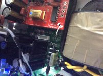
You can see the small coax in the picture. The I/O gets the clockpulse and the oscillator board the ground. Must i then disconnect the ground from the coax ? There is allready a common ground with all the powersupplies and leaving it like this would cause a loop.
second question, does it really matter where i attach the fan, ac or dc side.
if all loads are connected to the central powersupply at the dc side, then also are all the grounds.
You can see the small coax in the picture. The I/O gets the clockpulse and the oscillator board the ground. Must i then disconnect the ground from the coax ? There is allready a common ground with all the powersupplies and leaving it like this would cause a loop.
second question, does it really matter where i attach the fan, ac or dc side.
No, certainly not: transmission lines must be left alone and do their thing, no matter.Must i then disconnect the ground from the coax ? There is allready a common ground with all the powersupplies and leaving it like this would cause a loop.
In the case of an electrostatically shielded cable, it is frequently preferable to leave one of the shield sides open, precisely because of ground loop issues, but for a coax used as such, it must be properly terminated.
This has to be taken as a given of the problem, when you initially decide about the structure of the ground system, which is why I talked about the different options: in some cases, having an iterative system, where the ground and the essential supplies follow the path of key signals, like the master clock can be the best solution.
This means that the coax braid will also carry the return currents of the supplies, but this path can be fortified by an additional ground cable of hefty size following exactly the same physical path as the coax.
Sometimes, it is difficult to adhere to a deterministic scheme, because the network of different coax cables resembles a random spider web.
In this case, the best solution is to join the different elements through direct, low impedance paths, like thick braids (making them ~equipotential, but remember that in our universe, fundamental laws mean that true equipotentiality is just an aspiration), and use coaxials normally, but with common mode ferrite beads threaded on each cable, to lower the screen cutoff frequency and let them work as transmission lines, without parasitic concurrent paths
I do not really understand your question: the fan is either DC or AC, low voltage fans are mostly DC, which dictates the source.second question, does it really matter where i attach the fan, ac or dc side.
Since a fan is normally completely floating (unless you use alarm or temp. monitoring options), you can connect it where it suits you best, keeping in mind that the motor driver is not completely clean and can inject differential-mode disturbances.
- Status
- This old topic is closed. If you want to reopen this topic, contact a moderator using the "Report Post" button.
- Home
- Amplifiers
- Power Supplies
- when using 1 tranformer for 3 loads.