I saw this LM317/337 Servo Rectified Filtered Power supply board for sale.
LM317 / LM337 +/-1.5V~37V Adjustable Dual Voltage Regulator Power Supply Module 699985741185 | eBay
As usual, the seller does not include any schematic. How does the LF353 servo opamp work in this PSU circuit? What advantage does it have over the simple LM317/337 PSU?
The target application is a headphone amplifier using class A circuit.
Last edited:


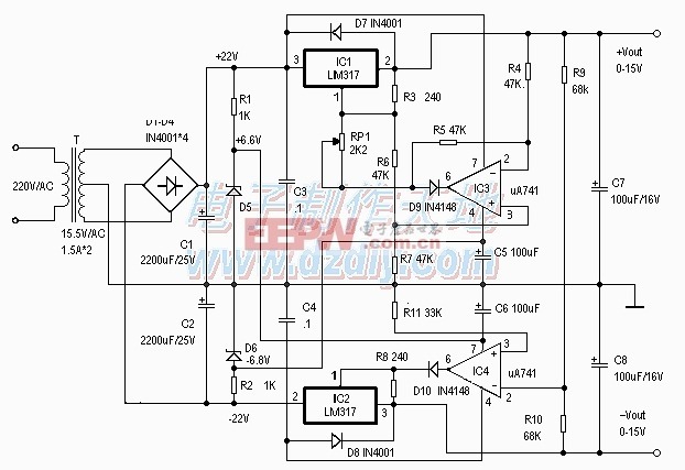
Keilau, I think the purpose of the opamp in the schematic you show for "servo, rectifier, filter power supply board" is to take the ripple and noise from the output of the power supply, invert it, and feed it back into the lm317/337, thereby cancelling the ripple and noise on the output. Hence the "servo" in the title. I think the circuit was originally designed by a poster on this forum, maybe apex audio, but I'm not sure.
chalky, I agree with you that the servo in the PCB seller posted circuit is likely for noise and ripple reduction. In this circuit, the servo takes the input from the same side of the output rail. I hope that some user may take some measurement of the LM317/337 pair with and without the servo to see how effective it is.Keilau, I think the purpose of the opamp in the schematic you show for "servo, rectifier, filter power supply board" is to take the ripple and noise from the output of the power supply, invert it, and feed it back into the lm317/337, thereby cancelling the ripple and noise on the output. Hence the "servo" in the title. I think the circuit was originally designed by a poster on this forum, maybe apex audio, but I'm not sure.
The servo can be used for output rail balance tracking as samsara suggested using his schematic. But it is a different topology. In the samsara schematic, there is only one trimmer on the positive side for output rail voltage adjustment.
When I tried to build a +/-15V PSU many years ago using the LM78xx/79xx pair, I could not get a close enough match of the output rails. I ended up using a very expensive tracking voltage regulator, Raytheon RC4195TK.
chalky, I agree with you that the servo in the PCB seller posted circuit is likely for noise and ripple reduction. In this circuit, the servo takes the input from the same side of the output rail. I hope that some user may take some measurement of the LM317/337 pair with and without the servo to see how effective it is.
The servo can be used for output rail balance tracking as samsara suggested using his schematic. But it is a different topology. In the samsara schematic, there is only one trimmer on the positive side for output rail voltage adjustment.
When I tried to build a +/-15V PSU many years ago using the LM78xx/79xx pair, I could not get a close enough match of the output rails. I ended up using a very expensive tracking voltage regulator, Raytheon RC4195TK.
An interesting observation but is a UA741 fast enough for that?
You right, it's the right schematic, not mine.I found this schematic from a PCB seller. It looks like the same circuit.
Here it show complete PCB
LM317/LM337 DC Servo Adjustable Voltage Regulator Board, Positive and Negative Dual Band Rectification Filter-in Air Conditioner Parts from Home Appliances on Aliexpress.com | Alibaba Group
Link to the English Alibaba website.You right, it's the right schematic, not mine.
Here it show complete PCB
LM317/LM337 DC Servo Adjustable Voltage Regulator Board, Positive and Negative Dual Band Rectification Filter-in Air Conditioner Parts from Home Appliances on Aliexpress.com | Alibaba Group
Aiyima LM317 / LM337 +/ 1.5V 37V Adjustable Dual Voltage Regulator Power Supply Module-in Voltage Regulators/Stabilizers from Home Improvement on Aliexpress.com | Alibaba Group
- Status
- This old topic is closed. If you want to reopen this topic, contact a moderator using the "Report Post" button.
- Home
- Amplifiers
- Power Supplies
- How does "LM317/ 337 Servo Rectified Filtered Power Supply" work?