hi
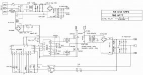
i use this schematic as my amplifire power supply
but i need about +-37 volt and this circuit is +-50 volt
i remove 11v zener for about +-37 volt but when i remove it the voltage is +38 and -40
primary turn in transformer is 24 turn and secendary is 2*7 turn
why voltage become +38/-40 when i remove 11v zener?
and how can i have +-37 in output?
Attachments
The 36v zener will drop 36volts but the led in the Opto Coupler needs about 2volts to switch on. Use a 34volt zener. There may be an imbalance with the -ve supply as it is not directly regulated.
To regulate both supplies, use a zener of 72volts in total and take pin 2 of the Opto Coupler to the -line instead of the zero point.
That will regulate across both lines and if the load is equal, the zero volt point will be in the centre.
To regulate both supplies, use a zener of 72volts in total and take pin 2 of the Opto Coupler to the -line instead of the zero point.
That will regulate across both lines and if the load is equal, the zero volt point will be in the centre.
thanks
when i have 24 turns in transformer primary and 2*9 in secandary an 36+11v zener(schematic numbers) the output voltage is +47.861 and -47.862 that is very balance but in this situation(24turn/2*9turn) when i remove 11v zener voltage become imbalance and about +38 and -40 .i want to know reason of this imbalance when i remove 11v zener ?
then i remove 2 turns in secendary(24turn/2*7turn) also remove 11v zener the output voltage was +38/-39(in my first post 39 instead of 40)
when i connetc opto pin2 to negative point and use 36+11+11+11v zener, output voltage is +35.7/-36.1
what is the resaon of these imbalance?
and when i use exact schematics numbers why output voltage is balance?
I think, there are two problems.
First
The 2n45 is an analog coupler. The collectorcurrent is depending on the diode current. So the diode current is about 4mA in normal operation (50V-36V-11V-1V(coupler Uf for low currents and 30°C)=2V 2V/510Ohms=4mA). If you want a +-37V supply, i would consider a 33V Zener and a 750Ohm Resistor (37V-33V-1V=3V 3V/4mA=750Ohm).
Second
In my opinion there are some small issues. The sg3525 is a closed voltagemode control loop converter. And there is a huge need for a phase-boost compensation for the feedback. If the feedback ratio is changed, the gain will be changed too and that means, that the ac behavior is not the same. It is possible, that the converter control loop is not stable any more during high power transients. But this is not the reason why the supply isn’t balanced any more. The output is not fully regulated, only the positive voltage is regulatet, so i think, the sg3525 is not the reason why there is an inbalance. In my opinion, there is only one part, which can generate this inbalance, the transformer. With the original configuration, the duty cycle is near 50%. What you do is removing 2 windings from the secondary and your feedback demands a voltage of 39V (4mA*510Ohm+36V+1V) the duty cycle will be not the same. What i think is, that the on time (of the highside fet) is longer than the off time. Then the sinusoidal current is not reallay sinusoidal any more. The positive curve will be flattend and the negative will be more spiky. But they have the same area (that means the same energy). The rectifier will show you the peak voltage. I think, that the voltage will be balanced with a load.
These are only assumptions. Without measurements i can only guess whats happening.
First, i would reduce the zener voltage and adjust the resistor. If the behavior doesn’t change, you will have to measure some details.
Do you have an oscilloscope? Can you measure the different duty cycles and the transformer’s secondarys?
You have an excellent technical explanation above,read it as long as itv takes to fully understand it.
Or, Plan B: your amplifier is perfectly fine with +37/´40V.
Or to be more precise, replace 37V zener with a 34V one as suggested above, so you are closer to rail voltage you expect.
That one is 1V above and the other 1V below what you want is of absolutely no importance.
Or, Plan B: your amplifier is perfectly fine with +37/´40V.
Or to be more precise, replace 37V zener with a 34V one as suggested above, so you are closer to rail voltage you expect.
That one is 1V above and the other 1V below what you want is of absolutely no importance.
thanks a lot broI think, there are two problems.
First
The 2n45 is an analog coupler. The collectorcurrent is depending on the diode current. So the diode current is about 4mA in normal operation (50V-36V-11V-1V(coupler Uf for low currents and 30°C)=2V 2V/510Ohms=4mA). If you want a +-37V supply, i would consider a 33V Zener and a 750Ohm Resistor (37V-33V-1V=3V 3V/4mA=750Ohm).
Second
In my opinion there are some small issues. The sg3525 is a closed voltagemode control loop converter. And there is a huge need for a phase-boost compensation for the feedback. If the feedback ratio is changed, the gain will be changed too and that means, that the ac behavior is not the same. It is possible, that the converter control loop is not stable any more during high power transients. But this is not the reason why the supply isn’t balanced any more. The output is not fully regulated, only the positive voltage is regulatet, so i think, the sg3525 is not the reason why there is an inbalance. In my opinion, there is only one part, which can generate this inbalance, the transformer. With the original configuration, the duty cycle is near 50%. What you do is removing 2 windings from the secondary and your feedback demands a voltage of 39V (4mA*510Ohm+36V+1V) the duty cycle will be not the same. What i think is, that the on time (of the highside fet) is longer than the off time. Then the sinusoidal current is not reallay sinusoidal any more. The positive curve will be flattend and the negative will be more spiky. But they have the same area (that means the same energy). The rectifier will show you the peak voltage. I think, that the voltage will be balanced with a load.
These are only assumptions. Without measurements i can only guess whats happening.
First, i would reduce the zener voltage and adjust the resistor. If the behavior doesn’t change, you will have to measure some details.
Do you have an oscilloscope? Can you measure the different duty cycles and the transformer’s secondarys?
i havn't oscilloscope but i do what you say and check the output again
i have anoher question how you calculate duty cycle in original configuration?
i calculate duty cycle(org config) by this formula:
Vin max=51 *(n=24/9) / Vpri=155
which resault is 89%!!
With this kind of formula, you can only calculate a continious conducting single coil power supply. The output voltage is defined by the energy storage in the coil. And the ratio of the dutycycle and the inputvoltage define the outputvoltage (the exact formula depends on the topology). A flyback converter got a similar formula. But this is a forward converter and a transformer can only deliver/transport energy from the primary to the secondary by changing the amount of current di/dt (for example a sine or a rectangular or a triangle…). If there is a dutycylce of 100%, no energy is transported to the secondary’s and the outputvoltage will be 0V.
Well, you can’t calculate an exact value of the dutycycle, because the primary coil is floating. In addition the dutycycle will change, if the load changes (voltage mode control loop).
The primary got 24 windings and the secondary’s got 9. If the current is sinusoidal and the peakvoltage is 310V on the primary, it would be:
Vsec=310V/2 * 9/24=58V(peak)
Then there are some copper and diode losses, so it is about 55V at light loads. So if there is a dutycycle of 50%, and we assume, that the current is sinusoidal, the outputvoltage is about 55V.
So the feedback voltage is too high and the control loop will reduce the amount of energy in two possible ways.
Puls skipping for very light loads. That means the dutycycle will be 0% for a few periods.
Or a reduced dutyclycle to a value between 25% (the exact value is defined by the capacity on the primary an the leakage inductance of the transformer) and 50% for light and normal loads. If the dutycycle is under 50%, the capacitor will help to form a sinusoidal current.
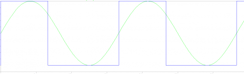
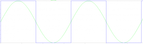
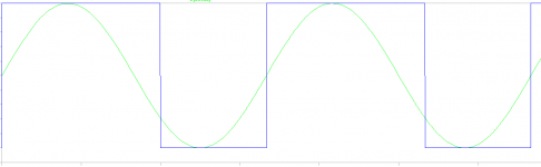
In the 3 pictures below, you can see a 40% a 50% and a 60% dutycycle compared with a sine wave. If the dutycycle is more than 50%, it will force a current through the primary (a flatened and longer sine at the positive output) and the LC series circuit will increase the voltage during the negative half wave (a spiky sine at the negative output). So i think the dutycycle at light loads is about 25%-45% and at heavy loads near 50%.
If your test with the adjusted feedback fails, you should try to add one winding to your secondary’s (not 7 windings, 8 windings or if it’s possible, add a half winding). This will reduce the dutycycle and you should get a more balanced output.
Well, you can’t calculate an exact value of the dutycycle, because the primary coil is floating. In addition the dutycycle will change, if the load changes (voltage mode control loop).
The primary got 24 windings and the secondary’s got 9. If the current is sinusoidal and the peakvoltage is 310V on the primary, it would be:
Vsec=310V/2 * 9/24=58V(peak)
Then there are some copper and diode losses, so it is about 55V at light loads. So if there is a dutycycle of 50%, and we assume, that the current is sinusoidal, the outputvoltage is about 55V.
So the feedback voltage is too high and the control loop will reduce the amount of energy in two possible ways.
Puls skipping for very light loads. That means the dutycycle will be 0% for a few periods.
Or a reduced dutyclycle to a value between 25% (the exact value is defined by the capacity on the primary an the leakage inductance of the transformer) and 50% for light and normal loads. If the dutycycle is under 50%, the capacitor will help to form a sinusoidal current.
In the 3 pictures below, you can see a 40% a 50% and a 60% dutycycle compared with a sine wave. If the dutycycle is more than 50%, it will force a current through the primary (a flatened and longer sine at the positive output) and the LC series circuit will increase the voltage during the negative half wave (a spiky sine at the negative output). So i think the dutycycle at light loads is about 25%-45% and at heavy loads near 50%.
If your test with the adjusted feedback fails, you should try to add one winding to your secondary’s (not 7 windings, 8 windings or if it’s possible, add a half winding). This will reduce the dutycycle and you should get a more balanced output.
Attachments
I simulated the curciut, but i don't understand every detail of the result. A normal half bridge forward converter works without the 1µF capacitor next to the transformer. i tried to explain how it works with the capacitor in my post before, but it was not completely right. The simulation says, that the dutycycle has no influence to the outputvoltage from DC+ to DC-. And the dutycycle has to be about 50%, if it's not, the outpup will be unbalanced. But it makes no sense, to use a voltage mode control loop, which can only vary the dutycycle to adjust the output. I think, that the chip is only used as an oscillator und as a maximum current limiter.
That means, that the transformer ratio is the only way to adjust the output, and the feedback has to be exactly the same as before to set the 50% dutycycle.
To understand, why the developer used the capacitor, i need some oscillograms. But i think, it's just an unregulated power supply. I think, that the outputvoltage decreases with the a larger output load. That means, that the converter has no controlloop and it's unregulated
To understand, why the developer used the capacitor, i need some oscillograms. But i think, it's just an unregulated power supply. I think, that the outputvoltage decreases with the a larger output load. That means, that the converter has no controlloop and it's unregulated
Well, it's not really unregulated, but if the output changes during a load step, the feedback will change the dutycycle, and the output will be unbalance and the positive output will be set to the right voltage. It's only during load steps or using a wrong feedback. If the feedback is just right to the transformer's ratio, the dutycycle is 50% and everything is fine.
Effectively you have to adjust the feedback to your transformer ratio. Maybe it's not possible to get a balanced +-37V output. With 7 windings on the secondary's it would be about +-39V and with 6.5 windings +-36V and with 6 windings +-33V. You can use the formula of my former post for a first approximation for the feedback and check the balance. If it's unbalanced again, you should change the resistor value und measure it again. i hope, i haven't confused you with my posts. If you have any questions, i would like to answer them.
thank you very much broWell, it's not really unregulated, but if the output changes during a load step, the feedback will change the dutycycle, and the output will be unbalance and the positive output will be set to the right voltage. It's only during load steps or using a wrong feedback. If the feedback is just right to the transformer's ratio, the dutycycle is 50% and everything is fine.
Effectively you have to adjust the feedback to your transformer ratio. Maybe it's not possible to get a balanced +-37V output. With 7 windings on the secondary's it would be about +-39V and with 6.5 windings +-36V and with 6 windings +-33V. You can use the formula of my former post for a first approximation for the feedback and check the balance. If it's unbalanced again, you should change the resistor value und measure it again. i hope, i haven't confused you with my posts. If you have any questions, i would like to answer them.
i found the problem
IR2110 Vcc pins(3&9) was not connected!!! and ir2110 was off
but in that situation every thing was ok and i had the voltage in output under load(inbalance)
but now i connect vcc to ir2110 and voltage is balance
and question is how circuit was working without ir2110!!!!
- Status
- This old topic is closed. If you want to reopen this topic, contact a moderator using the "Report Post" button.
- Home
- Amplifiers
- Power Supplies
- half bridge power supply