Refresh")
LOL. Impatient. Let's, slowly, use LTSpice to do this.
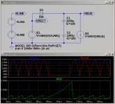
Starting with the input supply .asc attached. The line voltage is created using VLINEA and VLINEB converted to a rectified simile using B1. That is applied through D1 to your filter capacitors, C1 and C2, which are loaded by B2. Right click on a few things to get some idea as to what is going on.
B2 is set to draw a current based on VBUS equivalent to your suggested 500W load. VLINEA/VLINEB act to simulate a 220VAC line voltage with a single cycle line drop-out occurring at 1 second. This depends on how much you care and the regulatory standards you are working to. A single cycle line drop-out is a common requirement.
Picture 1) is the circuit including the simulation results.
Your most recent circuit shows you have used 470uF capacitors for your bulk supply. I have used 1000uF. If you change the values in the circuit to 470uF then things will fall over. VBUS gets down to 0V and the load current shoots off to a divide by zero error. That is what happens with a constant power load.
You can look to chase about trying to find a more acceptable answer, the tool is there, but I will stick with 1000uF and a minimum VBUS of 210V. Otherwise, for the moment, I am not taking losses or other factors into account. Those might be considered later.
Attachments
Well. That's a Bit Embarrasing
I forgot that the half bridge suffers from a midpoint instability when operated using current mode control. Since I am, in effect, implementing a corollary of current mode control my circuit is broken.
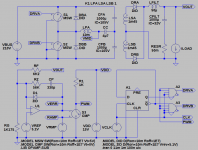
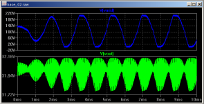
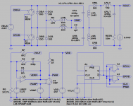
Anyway. Basic 'ideal' model of the converter attached and a couple of waveform plots showing it falling over. Although it is broken and may not exactly follow what you are trying to implement here are some words.
Top Left VBUS with two Switches and Diodes as the half bridge power stage. Transformer Primary Inductance and midpoint coupling capacitor with main bulk capacitors.
Top Right two secondary windings with ideal rectifier diodes the output filter inductor and capacitor along with its ESR. Loaded with a current sink.
Bottom Left the voltage error amplifier with reference and feedback/compensation components along with the RAMP and PWM comparator.
Bottom Right some logic to generate the drive waveforms for the half bridge. Right click on things to get some idea as to what is going on.
...
I forgot that the half bridge suffers from a midpoint instability when operated using current mode control. Since I am, in effect, implementing a corollary of current mode control my circuit is broken.
Anyway. Basic 'ideal' model of the converter attached and a couple of waveform plots showing it falling over. Although it is broken and may not exactly follow what you are trying to implement here are some words.
Top Left VBUS with two Switches and Diodes as the half bridge power stage. Transformer Primary Inductance and midpoint coupling capacitor with main bulk capacitors.
Top Right two secondary windings with ideal rectifier diodes the output filter inductor and capacitor along with its ESR. Loaded with a current sink.
Bottom Left the voltage error amplifier with reference and feedback/compensation components along with the RAMP and PWM comparator.
Bottom Right some logic to generate the drive waveforms for the half bridge. Right click on things to get some idea as to what is going on.
...
Attachments
All Hail Unknown Unitrode Seminar Attendant!
For the moment I cannot find where it is mentioned but someone solved this midpoint instability problem. So... being a plagiarist I'll use their idea to rescue myself.
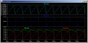
We get an additional primary winding, bother about that later, a couple of Clamp Diodes, DCx, and I have thrown in a current limiting resistor, RC, which might make it not work.
New .asc file attached along with a picture.
VOUT. We are in regulation.
VMID. Is now stable.
RAMP/VERR. We have slope matching.
...
For the moment I cannot find where it is mentioned but someone solved this midpoint instability problem. So... being a plagiarist I'll use their idea to rescue myself.
We get an additional primary winding, bother about that later, a couple of Clamp Diodes, DCx, and I have thrown in a current limiting resistor, RC, which might make it not work.
New .asc file attached along with a picture.
VOUT. We are in regulation.
VMID. Is now stable.
RAMP/VERR. We have slope matching.
...
Attachments
Last edited:
Welcome after the break.
Thanks for your commitment. At the moment I have another problem - I replaced LM358 with LM293 for comparator, but I didn't notice it's open collector output and it doesn't work properly. On the other hand, I already have a PCB made. In this situation, I think I am forced to use the opamp as a comparator. The question is which opamp will be fast enough at 50kHz? Could you suggest something?
Thanks for your commitment. At the moment I have another problem - I replaced LM358 with LM293 for comparator, but I didn't notice it's open collector output and it doesn't work properly. On the other hand, I already have a PCB made. In this situation, I think I am forced to use the opamp as a comparator. The question is which opamp will be fast enough at 50kHz? Could you suggest something?
Common ground-sensing op-amps vs. slew rate:
- LM358 is rated 0.3V/us in some datasheets, no information in others
- MC33171/2/4 series is rated about 2V/us
- MC33272/4 series is rated 10V/us
I have seen your schematic on PDF. When drawing schematics please leave room for the reference designator label and the value label of the parts.
EDIT: I often see a single capacitor across diode bridge outputs in mains rectification applications. From the point of view of safety approvals this is sub-optimal. Two capacitors, one from each AC input to each DC output of the bridge, in the range from 10nF to 100nF, produce a centering effect in mains live section of SMPS, thus reducing RMS voltage across insulation requirements, thus reducing required creepage in transformer and PCB. Common figures are 6~8mm but that can be reduced to 3~4mm. For more information read IEC 60095 and IEC 60650 standards (sometimes can be found in p2p networks, for diyers).
Last edited:
- LM358 is rated 0.3V/us in some datasheets, no information in others
- MC33171/2/4 series is rated about 2V/us
- MC33272/4 series is rated 10V/us
Thank You, but what speed is enough to keep it safe?
EDIT: I often see a single capacitor across diode bridge outputs in mains rectification applications. From the point of view of safety approvals this is sub-optimal. Two capacitors, one from each AC input to each DC output of the bridge, in the range from 10nF to 100nF, produce a centering effect in mains live section of SMPS, thus reducing RMS voltage across insulation requirements, thus reducing required creepage in transformer and PCB. Common figures are 6~8mm but that can be reduced to 3~4mm. For more information read IEC 60095 and IEC 60650 standards (sometimes can be found in p2p networks, for diyers).
Sorry, I didn't understand, which capacitors You mean?
What speed is enough? Simulate the op-amp circuit. How much input voltage is available? How fast the output has to toggle?
I mean the capacitor at diode bridge output in schematic of post #6.
Consider that TL07x/08x and similar do not work with input voltages close to negative rail, these are not "single-supply ground-sensing" op-amps, actually these TI JFET op-amps can sense voltages equal or above positive rail. Conventional op-amps stop responding when inputs get closer than 1~3V to either rail. On the other hand, usual comparators (like LM393) are ground-sensing. To pick an op-amp these requirements shall be analyzed. (There is also more modern stuff, rail-to-tail input-output.)
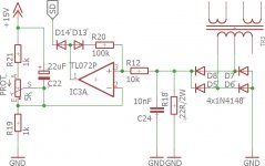
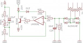
I changed a little the circuit (attached sd.jpg). As You may see, it's smps short-circuit protection. Assuming current transformer ratio 1:30 and power of 300W, primary current should be ~2A (300W/150V) and resistor at secondary side of CT is 22R (with 10nF capacitor), so there should appear ~1,5V and that value should toggle comparator (op-amp) output into high.
I do not know how fast it should be done. Switching requency is set to 50kHz.
I do not know how fast it should be done. Switching requency is set to 50kHz.
Attachments
- Status
- This old topic is closed. If you want to reopen this topic, contact a moderator using the "Report Post" button.
- Home
- Amplifiers
- Power Supplies
- Please, check my SG3525 driver state