... got admonished for presenting something similar to what you are proposing....
I don't know what was discussed then.
I don't see that power supply DC impedance is significant on a Class A SE circuit. The DC demand is constant.
AC impedance matters, but that is all down to your meager 5uFd cap at the end. That's 1K at 33Hz. Your OT primary may be in this general zone. Assuming 25H, with 5uFd makes a 15Hz resonance. Now the 600r resistor damps that to Q=0.25, no big deal.
There are many ways to do it. The problem is the rare/valuable '45. If you can find an analog which runs at similar V and I, but "affordable" (you won't cry real bad if you "whoops") (2A3?) I would prototype on that and see what works best.
PRR: I have reworked the power supply sim to use a single 5R4 to provide the majority of the required voltage drop, so I don’t need the last RC filter any more, and will have a 140uF capacitor as the final. This sims a voltage of 320 or so, depending on the figure I use for regulation. I don't have access to my computer at the moment, but from what I recall, the regulation figure I used was 5%. If the regulation is a higher percentage, I end up with a higher voltage. I don’t know what the regulation actually is, but I can reduce voltage with a small value resistor in between the two LC sections if need be.
I am trying to work out a switching system for this amp that makes it impossible to feed the wrong B+ voltage or filament voltage to a tube. I have been mulling it over for a while, and I think the safest way is to have separate sockets for each tube type, along with a sequential switching system. So, for example, a heater on/off switch that feeds line AC to a second on/off/on switch that selects between the filament regulator for the 45 or the one for the 300B. This second switch would also send line AC to the third switch, which would be an on/off/on that allows AC power through to the fourth switch, which directs this AC to the correct winding for B+ to either the 45 or 300B. If this last switch directs B+ to a different socket for each tube, the only way to mess it up is by putting the wrong tube in the marked socket. If the corresponding tube is in the correct socket, it will be impossible to give it incorrect B+ or filament voltages. Filament voltage has to be present or there will be no B+. Also, it forces a staged start up of filament first followed by B+. This will also make for a fascinating and entertaining turn on procedure for the uninitiated guest (who probably already thinks I’m a bit crazy).
I am trying to work out a switching system for this amp that makes it impossible to feed the wrong B+ voltage or filament voltage to a tube. I have been mulling it over for a while, and I think the safest way is to have separate sockets for each tube type, along with a sequential switching system. So, for example, a heater on/off switch that feeds line AC to a second on/off/on switch that selects between the filament regulator for the 45 or the one for the 300B. This second switch would also send line AC to the third switch, which would be an on/off/on that allows AC power through to the fourth switch, which directs this AC to the correct winding for B+ to either the 45 or 300B. If this last switch directs B+ to a different socket for each tube, the only way to mess it up is by putting the wrong tube in the marked socket. If the corresponding tube is in the correct socket, it will be impossible to give it incorrect B+ or filament voltages. Filament voltage has to be present or there will be no B+. Also, it forces a staged start up of filament first followed by B+. This will also make for a fascinating and entertaining turn on procedure for the uninitiated guest (who probably already thinks I’m a bit crazy).
You can use a half-wave rectifier fed from the tap, to either a choke input or cap input supply. Choke input would give about 350V DC when loaded, less any rectifier/choke drops. You will need to be careful about grounding the CT because it has two lots of charging currents in it. The two DC supplies (high and low voltage) will need to share a common negative.
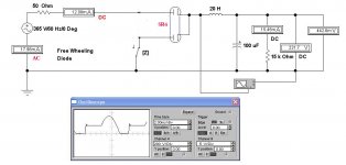
This is an old thread but needs a correction. Half wave rectification while using a cap input filter is OK. But not with choke input. There needs to be a way to maintain the current in the choke while the applied EMF goes -ve.
Otherwise the regulation of the cct will be poor. And some very objectionable ringing of higher frequencies will occur.
Best way is the so called 'free wheeling diode'. Commonly used in switch mode power supplies. A very low cost fix. And better still, it works. But seldom used these days in vacuum tube work. Refer to the attachments. Key 'Z' switches the diode in or out of the test circuit. Notice the spikes without the diode.
A useful addition to any rectifier circuit is a low value resistor, usually placed in the negative lead for tube type circuits. Typically it could be something like 10R, depends on other cct factors. A quick look can tell a lot, RMS vs Average current for example. It is the RMS current that cooks transformers. Choke input filter is better in this case.
Transformer designers spend a lot of time looking at Utility Factor, a measure of DC current available compared to the RMS current in the windings. All rectifier ccts experience harmonic currents in the windings. The result is heat.
Attachments
......not with choke input. ....
Thanks. It did not look right to me. Like a swing that only swings one way. Or me trying to turn the car in my snow-banked driveway: you can't go back-right if your nose can't slew left.
The diode freewheel is an idea. But all this "should" be simpler. Like a 1928 radio.
Using the 395-0 volt winding and a hybrid rectifier using two UF4007s and one 5R4 gets me around 325 volts B+ for the 45 tubes, and also allows choke input. For the 300Bs I would switch to the 520-0-520 volt winding, connect it to only the 5R4 and use the same LCLC filter for 425 volts B+.
jkstewart9 plan is definitely good to know for future reference.
jkstewart9 plan is definitely good to know for future reference.
One half of the 5R4 rectifier can be used as the free wheeling diode while the other half does the ordinary rectification. That way no extra parts or wiring are required.
With regard to the current capacity of the lower voltage winding, all one needs to do is check the winding resistance. It is most probably serially wound with taps brought out as required. Check the resistance from the CT of each end.
The lower voltage tap will measure the same ratio as the voltages. That means the cross section of the wire is the same all the way.
But only half the winding will be in use. The current capability will be less. But somewhat more than half, the temperature rise will not be as great.
Should be OK for your 45(s).
Attachments
Yes, you are correct. I should have thought of that. The result will then be 0.45 of the RMS AC voltage from the secondary.jhstewart9 said:This is an old thread but needs a correction. Half wave rectification while using a cap input filter is OK. But not with choke input. There needs to be a way to maintain the current in the choke while the applied EMF goes -ve.
Otherwise the regulation of the cct will be poor. And some very objectionable ringing of higher frequencies will occur.
Best way is the so called 'free wheeling diode'.
The limit set by the transformer spec on the HV Tap is probably to avoid DC core saturation. That would adversely effect the operation of the transformer.
Another way the proper supply voltage could be obtained is with a full wave bridge connexion, the transformer CT no longer on common (ground). Two arms of the bridge could be the 5R4, the other two arms silicon rectifiers. That way the DC biasing of the core does not occur.
Another way the proper supply voltage could be obtained is with a full wave bridge connexion, the transformer CT no longer on common (ground). Two arms of the bridge could be the 5R4, the other two arms silicon rectifiers. That way the DC biasing of the core does not occur.
My power supply will use two seperate power transformers, one each for the preamp and power tubes. I am assuming that I will also require two seperate filament transformers for the two rectifiers if I use the centre tap of one of them to get B+. If I don’t use the centre taps of the rectifier filament transformers to get B+, can I use one 5 Volt filament transformer for both rectifier tubes? This is new territory for me....
As the silicon diodes connect to the anodes and the heater connects to the cathode it is unclear what you think you mean by this question.tizman said:Also, I need to purchase a 5 volt transformer for the rectifier filaments. If I buy a centre tapped 5 volt transformer, can I use its centre tap for the B+ and avoid the two extra diodes?
You can use one 5V heater supply for more than one rectifier (i.e. join the heaters), provided that the rectifier cathodes are also joined. And, of course, the heater wiring is somewhere connected to the rectifier cathodes - many rectifiers do this internally, but if not you have to add an external connection.
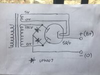
DF96: I tried to draw it out and realized that I was left without a ground that looks workable. I modified an organ amp once where the B+ came from the centre tap of the 5V rectifier filament winding, but in that case, if I remember correctly, the ground wire used was the centre tap for the B+ winding. I have attached a drawing of how I thought it could work with my power transformer, but it doesn’t seem right.
Attachments
There are several general purpose rectifiers with 5V heaters & two anodes. Commonly used in radio, TV & Hifi. Refer to the attached. Anyone of them would do for this cct. Switching HV is not recommended for the inexperienced. No ordinary switch would do well in this application.
If you see in a catalog of tubes a p/n beginning with 5 & ending in P1, P2, P7 & so on, that is a CRT, commonly used in an oscilloscope. The 'P' number indicate the color & attack/decay properties of the phosphor. P4 was used in TV.
The 5R4 series was more commonly found in Military/Industrial equipment. And might be an expensive choice buying new old stock (NOS). Something like the 5U4 series would do just as well.
For the bridge cct as drawn in your post of 5:52 PM today is correct. The diodes are part of the bridge configuration.The +ve lead still comes off the rectifier 5V heater transformer. The -ve lead comes from the center point of the silicon diodes. No CT is required on the HV winding of the B+ supply transformer.
Care is important, these voltages can be & are deadly. Even some of us with considerable experience still get whacked occasionally.
Which Class of operation do you intend to operate your 45s & 300Bs? Both are very expensive now. A simpler cct with common tubes would probably be a better choice if you are just starting out. The fact that you have those transformers should not be a factor while starting out. There are simpler & safer ways to go that deliver very good performance,
Attachments
DF96: It’s a bit late for that, as I’ve already built a couple dozen power supplies. Usually using a standard transformer that has B+ and all filament windings included. This is much more complicated, as I have two power transformers, one of which is a Hammond 274X for preamp duty, that has all filaments, and the other is a Freed power transformer with no filament windings. This means I will need to add two transformers for the heater filaments of the power tubes, one per Coleman regulator, and one transformer for the rectifier filament. Also, as the topic of this thread indicates, I would like to get two different B+ voltages out of the one Freed power transformer. With your kind assistance and that of the others that have contributed to this thread, I now have a game plan for building the amp and I have learned much. Thanks!
jhstewart9: I will use the schematic that you referred to as being correct. I have four NOS 5R4s on hand, and will use them for their required combination of voltage drop and high PIV. I am building an amp that will have two different circuits. Both are Class A. At the moment, I am considering Thorsten Loesche’s SV83/300B amp, and the Bugle 45 amp. It will be built with two chassis. One for power supply and one for the circuits. My primary motivation for doing this is to use a single set of output transformers for multiple amplifier circuits.
jhstewart9: What sort of switch would you recommend? As an alternate to the switch, I could install and wire two seperate rectifier sockets, one for each circuit, and insert the corresponding rectifier tube when I use the circuit. Is this a sensible alternative to a switch?
No you can´t , period.JMFahey: Yes, I need 70 mA for the two 45s and there is only 35 mA on the 395 volt tap. What I want to know is if it is possible to use just tap 4 and 6, or 4 and 6 with 5 as their center tap, to get a lower voltage from this transformer. I would use either this combination of taps for 45 tubes, or the normal 3-5-6 (520-0-520 volts) for 300B tubes, but never at the same time. I am using a seperate power supply transformer for the pre amp tubes, and will not use the 395 volt at 35 mA tap at all.
"Center tap" includes the meaning of *center* , that is exact halfway between 2 points.
5 is halfway/cen tap between 3 and 6.
It is NOT half way between 4 and 6 so it is not a Center tap; transformer will behave as if having 520V, only loaded in an inefficient way.
*Maybe* , but you actually don´t know.I believe if you are NOT sucking 250mA on the 520V legs, you could suck 125mA on the one 395V leg. They are surely all the same winding, gauge selected for like 140mA each side.
And wire is rated for full cirrent, not half of it.
Just duty cycle is 50% , but that´s something else.
Don´t mistakenly believe that since duty cyle is 50%,wire heating is also 50%, so "it´s as if it were 125mA all the time" which you seem to imply by your words above.
125mA 100% of the time is the same as 250mA half the time ... if we are talking average current.
BUT if we talk RMS (which describes its heating power), 250mA half the time is twice 125mA all the time.
Old time designers couldn´t save much copper section, if at all, by making "full wave" rectifiers; they made them just because only 2 plate common cathode tube rectifiers were widely available, and nothing else.
Last edited:
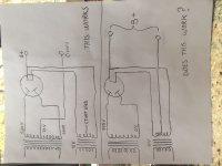
Your "Does This Work?" clearly does NOT work. It gives 2.5V AC where you seem to be expecting large DC.
That IS the "ideal" case for a naked-filament dual rectifier. Taking B+ from one end or the other adds/subtracts 5V on alternate waves, adding some 50/60Hz tone to the big 100/120Hz ripple.
But I once prodded a friend to 'scope it, and neither of us could see the difference (for a 400V supply, 5V rect).
And so many rectifiers are indirect-heat cathode, in which case the "ideal" connection is to that end of the heater.
...the B+ came from the centre tap of the 5V rectifier filament winding, ....
That IS the "ideal" case for a naked-filament dual rectifier. Taking B+ from one end or the other adds/subtracts 5V on alternate waves, adding some 50/60Hz tone to the big 100/120Hz ripple.
But I once prodded a friend to 'scope it, and neither of us could see the difference (for a 400V supply, 5V rect).
And so many rectifiers are indirect-heat cathode, in which case the "ideal" connection is to that end of the heater.
- Status
- This old topic is closed. If you want to reopen this topic, contact a moderator using the "Report Post" button.
- Home
- Amplifiers
- Power Supplies
- Best way to get different voltages from a tapped transformer