Hi All.
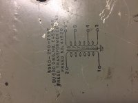
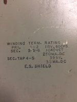
I’m hoping to get some advice on the best way to get two different voltages from a power transformer for a build I am planning that can use both 300Bs and 45s in the power tube position. The problem I am having is that the Freed power transformer I have (and I have 5 of them) is 520-0-520 @ 250 mA, with a tap for 0-395 volts @ 35 mA. I have attached a couple of photos of the specs/wiring diagram on the transformer for your consideration. I have worked out the power supply for a 300B using PSUD2, and with a 5R4 and a choke input, it’s at my desired voltage of 425 using the 520-0-520 winding. I am hoping to get 325 or so as well from this transformer using a switch to pick between windings. That would allow me to also use 45s in this amp. I’m not sure what would be the best way to get 325 out of this transformer, and I am hoping for some advice on the best way of doing so. Thanks in advance for your responses and advice!
I’m hoping to get some advice on the best way to get two different voltages from a power transformer for a build I am planning that can use both 300Bs and 45s in the power tube position. The problem I am having is that the Freed power transformer I have (and I have 5 of them) is 520-0-520 @ 250 mA, with a tap for 0-395 volts @ 35 mA. I have attached a couple of photos of the specs/wiring diagram on the transformer for your consideration. I have worked out the power supply for a 300B using PSUD2, and with a 5R4 and a choke input, it’s at my desired voltage of 425 using the 520-0-520 winding. I am hoping to get 325 or so as well from this transformer using a switch to pick between windings. That would allow me to also use 45s in this amp. I’m not sure what would be the best way to get 325 out of this transformer, and I am hoping for some advice on the best way of doing so. Thanks in advance for your responses and advice!
Attachments
You can use a half-wave rectifier fed from the tap, to either a choke input or cap input supply. Choke input would give about 350V DC when loaded, less any rectifier/choke drops. You will need to be careful about grounding the CT because it has two lots of charging currents in it. The two DC supplies (high and low voltage) will need to share a common negative.
DF96: To clarify my question, I would be using one winding at a time when using this transformer, and I would pick the appropriate winding, with a switch, for the tube that I want to use. If I understand you correctly, your answer allows me to use both simultaneously, but I don’t need to do this as I will be switching between one power supply connection to the other for the power tubes (300B and 45) and using a seperate power transformer for the preamp tube B+. What would I get if I used 4 and 6 with respect to voltage and available amperage? Sorry, I should have been more clear when I asked the question.
I hope you realize the lower voltge supply is probably meant for screens or preamp duty only and in no way you can feed a power tube from it.
To make it clearer: forget feeding a 45 (or *any* power tube) from it
.......
Think 0.9X to 1X instead and you´ll be closer.
To make it clearer: forget feeding a 45 (or *any* power tube) from it
.......
*Input Choke* ... the 1.4X factor does not apply here.520v x 1.4 = 728v.
How does this reduce to 350v?
Likewise,
395v x 1.4 = 553v (low voltage supply).
Think 0.9X to 1X instead and you´ll be closer.
Last edited:
JMFahey: Yes, I need 70 mA for the two 45s and there is only 35 mA on the 395 volt tap. What I want to know is if it is possible to use just tap 4 and 6, or 4 and 6 with 5 as their center tap, to get a lower voltage from this transformer. I would use either this combination of taps for 45 tubes, or the normal 3-5-6 (520-0-520 volts) for 300B tubes, but never at the same time. I am using a seperate power supply transformer for the pre amp tubes, and will not use the 395 volt at 35 mA tap at all.
...The problem ...is ... 520-0-520.., with a tap for 0-395 volts ...
I believe if you are NOT sucking 250mA on the 520V legs, you could suck 125mA on the one 395V leg. They are surely all the same winding, gauge selected for like 140mA each side.
But not (simply) with a common-cathode vacuum rectifier.
The choke value must increase because of the higher DC resistance.
The AC will be half-wave, 60Hz. The choke value must double, at least...
I am not sure a choke-input works properly with a half-wave supply.
(A Silicon FWB would work fine, but I suppose you are allergic.)
And I am not inclined to ponder that because....
There is a SIMPLE answer. 425V to 1.4K 20W resistor makes 325V @ 70mA. The fact that you *have* a 395V tap does not mean you must *use* the 395V tap. Problem gone.
Yes, there is 7 Watts of heat wasted. Big deal. If you can't stand the heat you can go to class D.
Attachments
PRR: Thanks. Yes, that works, but shouldn't that much series resistance in the power supply be avoided? I posted a PSUD2 sim once, and got admonished for presenting something similar to what you are proposing as a solution. It was a while back, and I was even less informed than I am now, so it stuck with me. If I recall correctly, I was told that it would hurt the dynamics of the amp to have too much resistance in the power supply. What are your thoughts on this? You are far more informed and experienced than I am and I would love to know if you think this is an actual or imagined problem. Thanks again for your input. It is always appreciated.
PRR: Also, I would be using the 45 as the power tube instead of the 300B, so the current required for the 300Bs isn't part of the sim. To get 325 volts or so, I would need a resistor of 1.9-2K according to PSUD2. I am not allergic to silicon, and your suggestion of using a FWB off of the 395-0 winding for the 325 volts @ 70 ma I need is something I am going to try simming next. Thanks for the insight about the 395-0 winding being able to draw more current when the main 520-0-520 winding isn't being used. That really opens up a lot more options. The 395-0 winding measures at 458 volts unloaded, which is 16% regulation, if I am reading the PSUD2 sim correctly.
Last edited:
You would get half-wave rectification from a circuit which looks like full wave.tizman said:What would I get if I used 4 and 6 with respect to voltage and available amperage?
Yes, probably.PRR said:I believe if you are NOT sucking 250mA on the 520V legs, you could suck 125mA on the one 395V leg. They are surely all the same winding, gauge selected for like 140mA each side.
It does, but only in the sense that you get 0.45 Vrms - which I forgot about. Thanks for reminding us.I am not sure a choke-input works properly with a half-wave supply.
So it seems you have two choices:
1. run a full-wave rectifier from the whole winding to get a high voltage supply.
2. run a bridge from the tap to get a lower voltage supply.
Switching between these two will be messy, and you cannot do both at the same time.
Best placement of voltage dropping resistor in power supply
Is there any benefit in placing the voltage dropping resistor elsewhere? For example, if I split its value in two, and put one resistor between the power transformer and rectifier on each leg that supplies 520 volts on the supply. I have tried moving the additional required 570 Ohms of resistance to other places in the circuit, but putting it before the last cap that feeds the B+ seems to result in the best power supply, according to my PSUD2 sims. I am unable to sim the placement of the resistance between the power supply and rectifier in PSUD2, so I don't know if it works better than the placement of the resistance at the end, as shown in the last sim I posted.
DF96: I won't throw that switch when it's powered. At least not on purpose....
Bear in mind that there is more to PSUs than correct DC voltage and low ripple. You may also need a sufficiently low output impedance at subsonic frequencies - which people often forget about. Simply adding dropping resistors can adjust DC and reduce ripple, but increase output impedance.
DF96: I would prefer to not add additional resistance in series to reduce the voltage to suit the 45 tubes. Without the additional required 570 Ohms, it would be a reasonably low resistance supply. I am building the power supply on a seperate large chassis, so I do have some room. I will be using two power transformers, one for power tubes, and the other for preamp tubes, so I could derive the 45 tube voltage from the other transformer, and use the 395-0 winding for the preamp tubes instead. This will probably require much more complicated switching. The other option is to use two 5R4 rectifier tubes in a full wave bridge to rectify the 395-0 winding. I haven’t simmed it yet, but it should drop the B+ from the 395-0 winding more than silicon rectifiers would and reduce the amount of resistance required in series. I’m not sure if this option also increases the output impedance at subsonic frequencies though.
- Status
- This old topic is closed. If you want to reopen this topic, contact a moderator using the "Report Post" button.
- Home
- Amplifiers
- Power Supplies
- Best way to get different voltages from a tapped transformer